SCHEMATIC


Material List
CONDENSERS
Mica C1 = 5000 pF 500V
Variable C2 = 25 pF 250V
C3, C4, C5 = 1000 pF 600v, (feedthrough by-pass)
C6 = 1000pF, 7500V, DOORKNOB
C7, C8 = 100pF, 15KV, DOORKNOB
"C9" not used
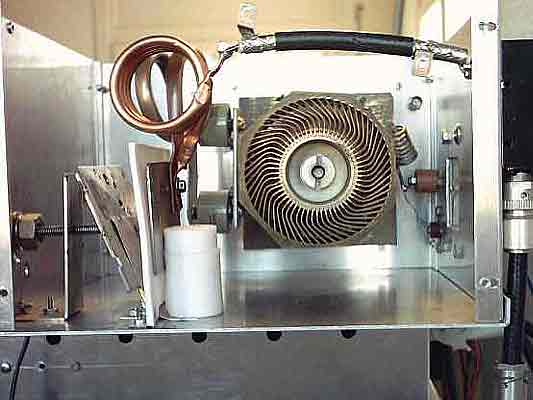
(**) C10 = 40pF
(**)Capacitor "sandwich" made of two
metallic plates separated by teflon sheet, 4mm thick.
The fixed plate of 80 x 70 mm, connected to the two coils, supported by a
piece of bar of teflon that isolates it from the chassis and maintains mechanical
rigidity.
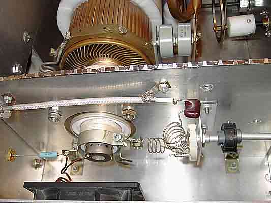
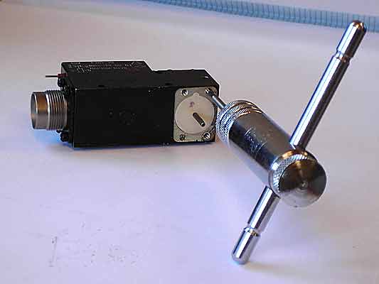
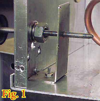
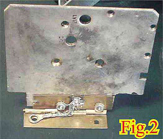
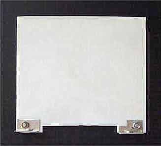
The tilted plate
(fig.2)
of 95 x 85 mm, is subject to the chassis by a brass hinge. In
order to move the plate a rod threaded "pusher" is used
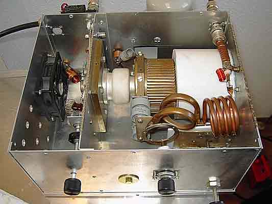
(fig.1)
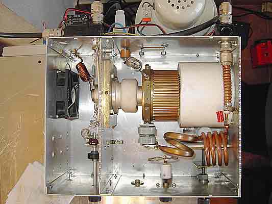
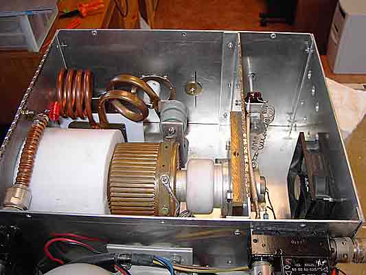
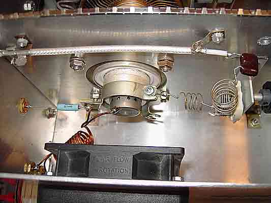
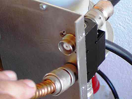
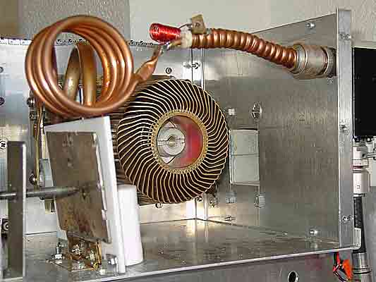
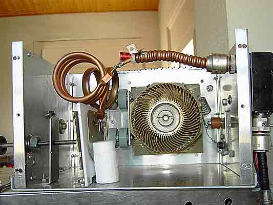
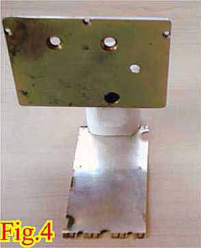
a laminate of beryllium copper (fig.3
and fig.4)
held to the base of the bar of teflon acts mechanically opposite
to the push of the rod and helps provide an optimal electrical
connection from the movable plate of C10 to chassis ground (fig.6).
C10 construction
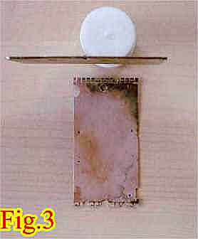
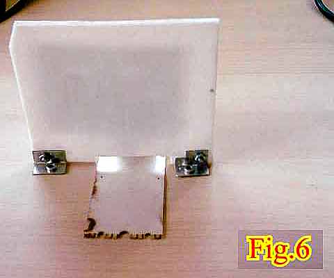
The holes in the metallic plates are due to use
of recycled material, coming from taking apart.
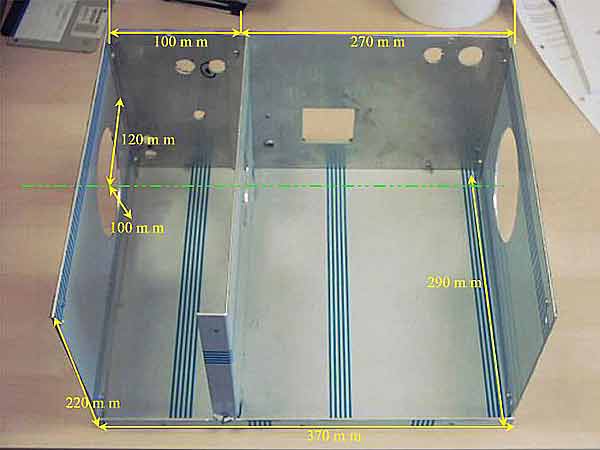
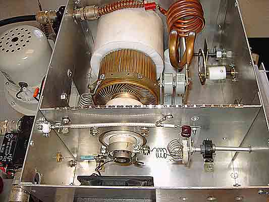
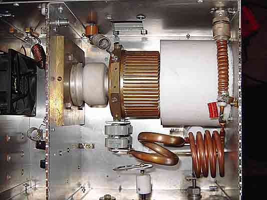
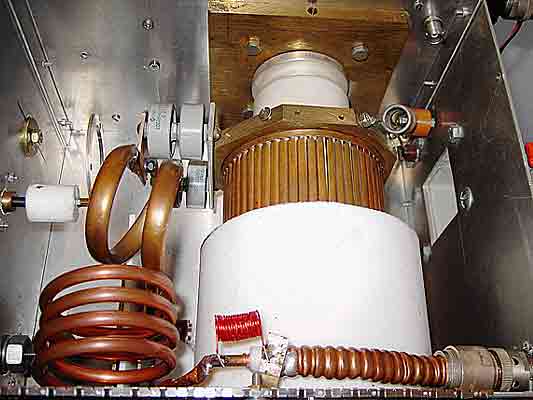
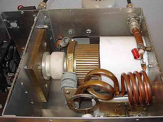
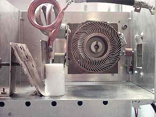
GS35B CLAMPS
The clamp that holds to the GS35b and the one of connection of the anode
is of aluminum or brass of 10mm of thickness; see the photos for
its implementation.
The chimney of the valve is teflon, 110 x 100 mm.
COILS
L1, L2 = 4 turns of 1mm silverplated wire, coil diameter = 16mm, lgt = 20mm.
L3 = Z-144 RF choke.
L4 = 11 bifilar turns of 2.5mm enameled wires, coil diameter = 16mm
L5 = 8 turns of 1mm enameled wire, coil diameter = 16mm, lgt = 30mm
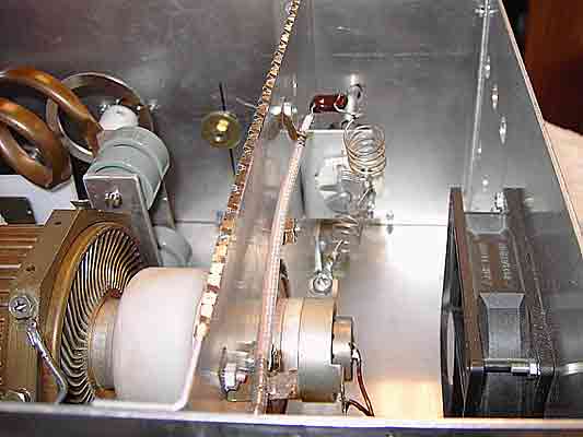
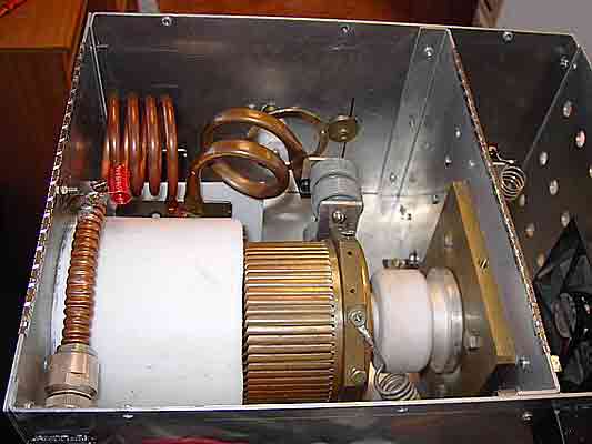
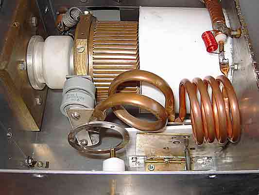
L6 = (*) 1.5 turns of 3/8" copper tubing, coil diameter = 45mm., lgt = 35mm
L7 = 4 turns of 1/4" copper tubing, coil diameter = 40mm, lgt = 50mm.
L8 = 20 turns of 1mm enameled wire, coil diameter = 10mm, lgt = 20mm
(*) See pictures, below
- For the adjustable part of L6, a silverplated brass hoop 6.25mm wide and 45mm inner
diameter is used; the original came from surplus homemade material.
- The dimentions are not absolutely critical and any hoop of similar dimensions can be used.
- The hoop is insulated from the chassis by an axis of insulating material (plastic, delrin or similar) and meeting of
teflón.

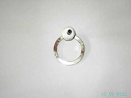
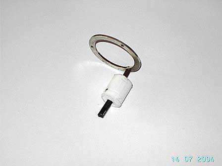
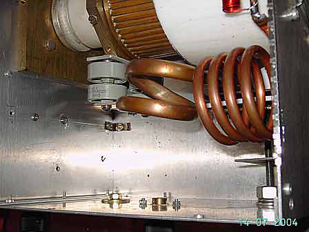
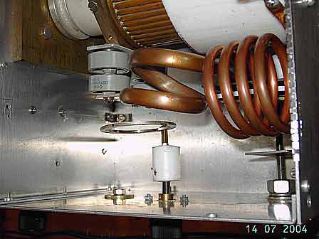
PLATE CONTROL and POLARIZATION
Instead of using the classic circuits of polarization and measurement I have used
TRIODE BOARD of
RF PARTS but also take a look at:
Barend Hendriksen of Holland.
The coaxial relays from UR4LL
Triode Board in RFPARTS or
DOWN EAST MICROWAVE.
If you do not find some material or you need information you can get in contact with me,
Quim, EAÁXV
 mailto:ea3axv@terra.es
Index