|
 This amplifier was designed for high-power, high duty cycle operation on the 2M band (144.000
to 144.200 MHz). It supports both CW and the high duty cycle
WSJT modes (FSK441,
JT44, JT65, etc) for EME and meteor scatter contacts. Linear amplification for SSB was not
desired. However, the base design would likely support this mode at lower power levels.
EDITOR'S NOTE: Go HERE to see operating
parameters supporting GS-23B linear operation.
This amplifier was designed for high-power, high duty cycle operation on the 2M band (144.000
to 144.200 MHz). It supports both CW and the high duty cycle
WSJT modes (FSK441,
JT44, JT65, etc) for EME and meteor scatter contacts. Linear amplification for SSB was not
desired. However, the base design would likely support this mode at lower power levels.
EDITOR'S NOTE: Go HERE to see operating
parameters supporting GS-23B linear operation.
The design uses a W6PO-derived output tank circuit (go HERE for calculations), and a T-input tuned circuit. It employs
a Russian GS-23B tetrode tube (4CX1600U), with the cathode driven by the input tank and at
47 VDC bias above the control grid, the control grid (G1) is grounded for both RF and DC, and
the screen grid (G2) is at RF ground but operates at 600 VDC with respect to the cathode. The
design parameters are based on a high plate voltage, roughly 3750 VDC under load. Here are the
design and typical operating parameters:
| Parameter | Range | @ 1500W output |
| Pin (drive to cathode): | 0 - 30W | 30W |
| Eg1 (wrt cathode): | -47 VDC (regulated) | -47 VDC |
| Ig1 (max): | 0 - 30 mA | 25 mA |
| Eg2 (wrt cathode): | 600 VDC (shunt regulated) | 600 VDC |
| Ig2: | -20 to +20 mA | 15 mA |
| Ep: | 3750 VDC | 3750 VDC |
| Ip: | 0 - 1.2A | 0.8A |
| Eff: | | 50-55% |
J1 - Type "N" connector, visible in the upper-right quarter of the cabinet rear view.
J2 - Type SO-239 connector, near the lower-center of the rear of the cabinet.
C1 - 680 to 1000 pF, 500VDC silver mica
C2 - Input tune; 2 - 20 pF, 500VDC air variable (values not critical)
C3 & C4 - 2 x 100 pF, 7.5KV or more, high RF amperage doorknob capacitors
C5 - tune capacitor, 4" X 2.5" Cu plates; separation variable from 1/4" to 3/4"
C6 - load capacitor, 1.75" X 1.75" Cu plates; separation variable from 1/4" to 3/4"
C7 - 1000 pF doorknob, 5KV or more; could use properly rated feedthrough, as well
C10 & C11 - 1000 pF feedthrough capacitors, voltage rating above 20VAC
Cg2 - 6 x 470 pF chip capacitors, Mouser 5982-22-1000V470
L1 - 4 turns #14 enamelled wire, 3/4" dia
L2 - 2 turns #14 enamelled wire, 3/4" dia
L3 & L4 - Filament choke, 13 closely packed bifilar turns, 3/4" dia.
L5 & L6 - Resonator pipes, 1 1/8" OD thinwall copper tubing, 8.5" long
L7 - Plate choke, 6 turns #14 3/4" dia
RFC1 - 10 turns of 24 over a 100 ohm 3 W metal oxide resistor or Ohmite Z-144
taps 5 & 16 - connect to 6.3 VAC filament supply
 The base chassis was the W6PO kit sold by
K3IWK. The chassis was assembled and the various components
mounted using short "standoffs" (Mouser 532-1560B). These standoffs were easy to install
with hand tools (a cone chisel was used to flare the standoff flange into the base cabinet
metal), and resemble the popular "PEM nuts" in operation. Much of the miscellaneous sheet
metal and tubing was obtained from
online metals. Click on picture for chassis details.
The base chassis was the W6PO kit sold by
K3IWK. The chassis was assembled and the various components
mounted using short "standoffs" (Mouser 532-1560B). These standoffs were easy to install
with hand tools (a cone chisel was used to flare the standoff flange into the base cabinet
metal), and resemble the popular "PEM nuts" in operation. Much of the miscellaneous sheet
metal and tubing was obtained from
online metals. Click on picture for chassis details.
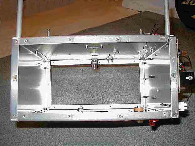
The tube "mounting box" (podest) was shortened to 4" (originally 6") high to provide more
clearance between the tube anode and the top of the amplifier enclosure.
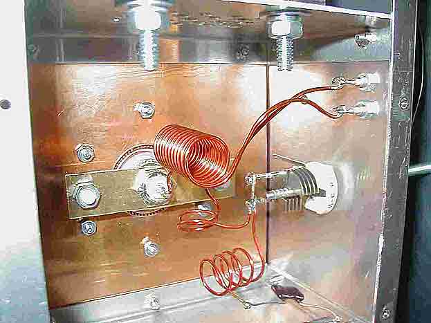
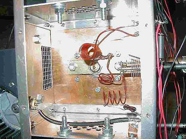 The pictures to left and right show the shortened "mounting box" and the input circuit wiring.
An SO-239 chassis mount connector is used to connect to the heater pin and cathode rings below the
G1 surface. The outer portion of the connector is mounted on a brass flange which is isolated
from the G1 surface by nylon bolts (this flange must float at 47 VDC with respect to G1, and
it will be driven by the tuned input circuit. A shortened 3/8" brass pipe nipple was used to
bush the outside of the SO-239; small fingerstock was used to form the connection between this
nipple and the cathode ring on the tube.
The pictures to left and right show the shortened "mounting box" and the input circuit wiring.
An SO-239 chassis mount connector is used to connect to the heater pin and cathode rings below the
G1 surface. The outer portion of the connector is mounted on a brass flange which is isolated
from the G1 surface by nylon bolts (this flange must float at 47 VDC with respect to G1, and
it will be driven by the tuned input circuit. A shortened 3/8" brass pipe nipple was used to
bush the outside of the SO-239; small fingerstock was used to form the connection between this
nipple and the cathode ring on the tube.
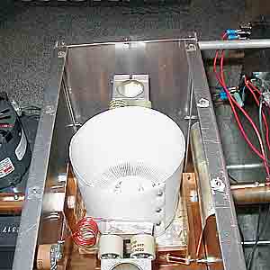 The GS-23B is located near the center, the plate load capacitor is to the left. The strap
connecting the movable plate to the "N" connector is visible. Above this is the doorknob bypass
capacitor, the plate choke, and the Millen HV connector. The two-doorknob set that blocks DC
from the resonator tubes is C10. Far right is the tune capacitor. Note that on the mechanical
apparatus that moves the capacitor plates that the teflon plug extends all the way into the
anode compartment. Also visible is the lock screw that prevents these plugs from rotating when
the knobs are turned, and the nylon mounting screw that holds the movable plate to the teflon
plug and also prevents the plates from getting too close. It is also clear that a teflon
chimney is constructed to vent air from the anode fins through the top of the amplifier. This
chimney must also insulate the chassis from the HV on the tube anode.
Click on picture for more construction details.
The GS-23B is located near the center, the plate load capacitor is to the left. The strap
connecting the movable plate to the "N" connector is visible. Above this is the doorknob bypass
capacitor, the plate choke, and the Millen HV connector. The two-doorknob set that blocks DC
from the resonator tubes is C10. Far right is the tune capacitor. Note that on the mechanical
apparatus that moves the capacitor plates that the teflon plug extends all the way into the
anode compartment. Also visible is the lock screw that prevents these plugs from rotating when
the knobs are turned, and the nylon mounting screw that holds the movable plate to the teflon
plug and also prevents the plates from getting too close. It is also clear that a teflon
chimney is constructed to vent air from the anode fins through the top of the amplifier. This
chimney must also insulate the chassis from the HV on the tube anode.
Click on picture for more construction details.
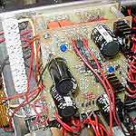 The "Tetrode Boards," developed by G3SEK and marketed by
Tom's Tubes were used to develop most of the DC voltages,
TR switching, and handle control and safety duties during amplifier operation. They were
built by closely following the instructions that come with the boards, "The Tetrode Boards
- Control and Protection for your Tetrode RF Power Amplifier." Given the operating conditions
for the GS-23B tube, However, and the requirements of the amplifier, several changes were made.
Click on picture for details on tetrode boards.
The "Tetrode Boards," developed by G3SEK and marketed by
Tom's Tubes were used to develop most of the DC voltages,
TR switching, and handle control and safety duties during amplifier operation. They were
built by closely following the instructions that come with the boards, "The Tetrode Boards
- Control and Protection for your Tetrode RF Power Amplifier." Given the operating conditions
for the GS-23B tube, However, and the requirements of the amplifier, several changes were made.
Click on picture for details on tetrode boards.
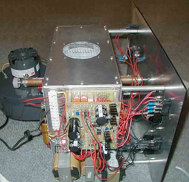
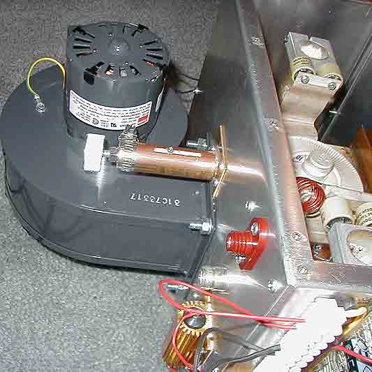 A conservative cooling circuit, based on a Dayton 4C006 blower, was designed to keep the
tube cool under long skeds involving the high duty cycles of the WSJT JT65 mode popular in
EME. The mechanical construction of this amplifier was purposely very robust to eliminate
thermal tuning drift or tuning sensitivity caused by external disturbances. The cooling
flow path is designed to keep the GS-23B cool under extreme duty cycle conditions. The
blower mounts to the back of the chassis with the motor shaft vertical and the air inlet
to the blower on the bottom. This arrangement both decreases the chance that a foreign
object can fall into the blower impeller (as it is pointed downward), and allows half of
the blower stream to be directed above the tube mounting box (podest), with the other half
used to pressurize the grid compartment. Hardware cloth is used to shield these inlet
rectangles such that RF cannot pass into the blower outlet. The grid compartment stream
cools the underside of the tube (the G1/cathode/heater area), the cathode flange, and the
input tank, then it leaves the grid compartment through holes drilled near the bottom of
the compartment. It then cools the resonator tubes and sides of the chassis, then rejoins
A conservative cooling circuit, based on a Dayton 4C006 blower, was designed to keep the
tube cool under long skeds involving the high duty cycles of the WSJT JT65 mode popular in
EME. The mechanical construction of this amplifier was purposely very robust to eliminate
thermal tuning drift or tuning sensitivity caused by external disturbances. The cooling
flow path is designed to keep the GS-23B cool under extreme duty cycle conditions. The
blower mounts to the back of the chassis with the motor shaft vertical and the air inlet
to the blower on the bottom. This arrangement both decreases the chance that a foreign
object can fall into the blower impeller (as it is pointed downward), and allows half of
the blower stream to be directed above the tube mounting box (podest), with the other half
used to pressurize the grid compartment. Hardware cloth is used to shield these inlet
rectangles such that RF cannot pass into the blower outlet. The grid compartment stream
cools the underside of the tube (the G1/cathode/heater area), the cathode flange, and the
input tank, then it leaves the grid compartment through holes drilled near the bottom of
the compartment. It then cools the resonator tubes and sides of the chassis, then rejoins
 the stream of air that was directed above the tube mounting box. The two streams then pass
through the tube anode fins, up the teflon chimney, and out of the chassis through the
hardware cloth shield on top of the cabinet (see picture at right). This shield reduces the
chance that objects will be dropped onto the tube anode and provides RF shielding. One
should enclose the final amplifier in a suitable rack such that screwdrivers and such
cannot be dropped past the hardware cloth. If this happens, the screwdriver shaft will
become energized to the tube anode potential of 4 kV, with possibly-disasterous results.
the stream of air that was directed above the tube mounting box. The two streams then pass
through the tube anode fins, up the teflon chimney, and out of the chassis through the
hardware cloth shield on top of the cabinet (see picture at right). This shield reduces the
chance that objects will be dropped onto the tube anode and provides RF shielding. One
should enclose the final amplifier in a suitable rack such that screwdrivers and such
cannot be dropped past the hardware cloth. If this happens, the screwdriver shaft will
become energized to the tube anode potential of 4 kV, with possibly-disasterous results.
Many hours of EME operation have shown that both the tube anode and base temperatures
remain quite cool with this cooling design, even at high elevations (7200 ft ASL). It is
not recommended that a smaller blower be substituted, however. The 4C006 is relatively
quiet given this design. Furthermore, the chassis remains quite cool, which adequately
dissipates the heat generated by Q2 and R12, and reduces any thermal tuning drift caused
by cyclical chassis heating to negligible levels.
|