144MHz 1.5KW GU-84b Linear Amplifier
|
|||||||||||||||||||||||||||||||||||||||||||||||||||||||||||||||||||||||||||||||||||||||||||||||||||||||||||||||||||||||||||||||||||||||||||||||||||||||||||||||||||||||||||||||||||||||||||||||||||||||||||
|
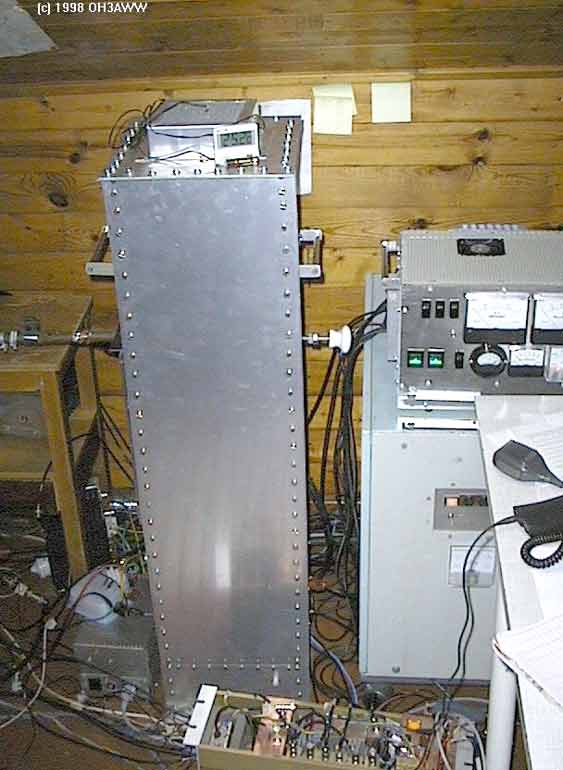
During the summer 1997 I completed my new GU-84b tetrode power amplifier. I used my
previous 4CX250R PA power supply for this (Picture 1). Because there have been a few
requests for construction information, I decided to write this article. Please do note
that this is not made for first PA project builder and I will not take any responsibility
about errors of this document.
|
|
GU-84b Tetrode
|
GU-84b is the military version of the Svetlana 4CX1600b. GU-84b is made for bigger
anode dissipation and current. It also needs more powerful blower than 4CX1600b
(picture 2, below).
|
||
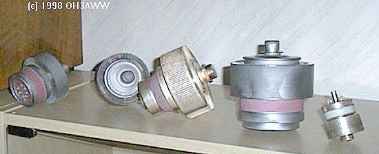 Picture 2: GU74b(x2), GS23b, GU84b and 4CX250R |
||
|
GU-84b socket has air chimney and cooling air is then feed through grid cabinet to
anode. Svetlana socket SK3A can also be used but in that case cooling air is feed
first to anode cabinet. Socket cooling is important and should not be forgotten.
The both sockets have a built-in Screen capacitor and therefore it is possible to
connect the cathode to the ground. GU-84b socket has also 0.5W
resistor for anode current measurement purpose.
|
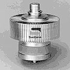  Picture 3: 4CX1600b & SK3A |
|
PA Working Conditions & Cooling
|
The power output with my power supply is about 1500 W in linear service.
The efficiency is about 65 %. Plate voltage is 1900 V @ 1.2 A. The tube
needs also 350 V on screen and –84 V (-120 V or more on rx) on grid (G1).
Filament uses 27 V @ 4A. GU-84b maximum anode dissipation power is 2.5 kW.
With this power the tube needs really big blower that can give 75 mm H2O
pressure and 2.5 mł/min airflow. With 1.6 kW dissipation tube needs 30 mm
pressure and 1.6 mł/min airflow. With my own experience at 1 kW output
level and HSCW (high speed CW) in meteor scatter mode the output air
temperature (20şC room temp) will change from 30şC®50şC
within one 2.5 min TX period. The blower is in separate box and cooling air is
feed in the 90 mm aluminium tube to PA. On TX the pressure is 32 mm and on RX
20 mm in the input cabinet. Smaller fan could also be used as can be seen from
air temperature.
|
Power Supply
|
The filament PSU is 27 V @ 4 A DC with current limit circuit. This feature is good
for a soft start. I use a L200 regulator and a pair of 2N3055 transistor for this
circuit. The filament resistance is 2.5W when it is cold
and it takes 3 seconds until current is below 4A. The tube manufacturer recommends
that cooling should remain up to 5 minutes after filament is turned off.
|
PA construction
|
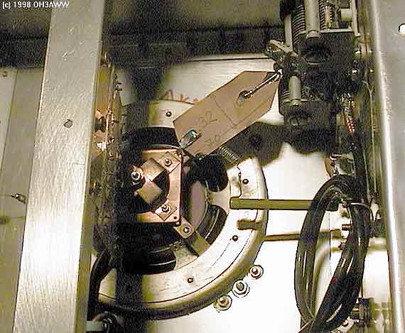
The plate is a ˝ l coaxial resonator and grid an LC circuit. Before
building I recommend visiting SM5BSZ
homepage to see what Leif says. The input is directly from there and the Q-value is
decreased with the resistor. But still the gain is about 16 dB. There is no
need of neutralizing the PA with this construction.
|
|
|
|
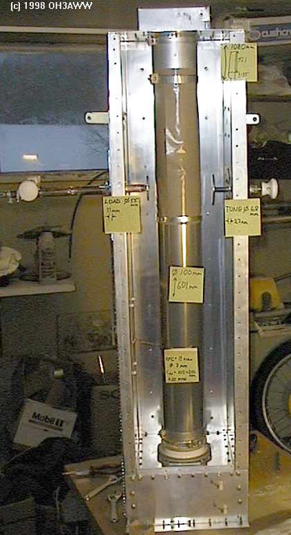
| Picture 4: Plate Line Construction | |||
|
At first I had difficulties to find the right length of the anode resonator. With the help
of Jukka, OH1FF I found the correct resonator length. Because of this the cabinet is about
200 mm longer than needed and there are extra holes for tune and load capacitors. However
now it is possible to change the tube to 4CX1600b. It needs 75 mm longer resonator.
|
|
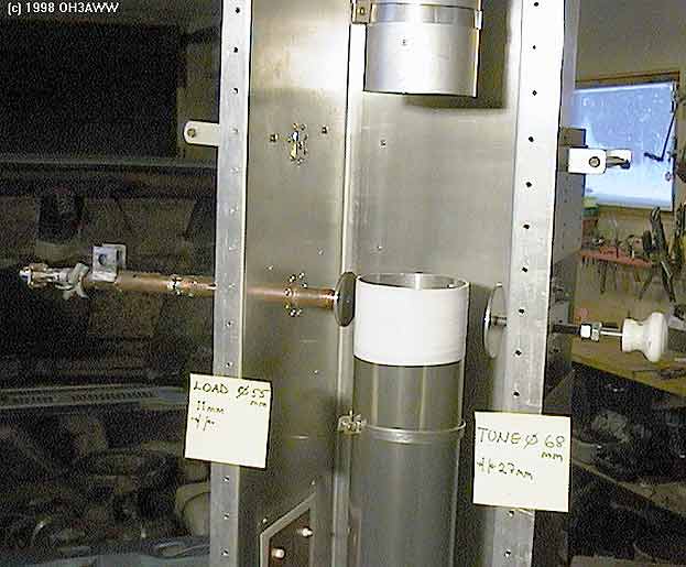 |
Output load and tune are both capacitive because more simpler mechanics than inductive version
(Picture 5). The efficiency is now a little bit worse with this construction.
|
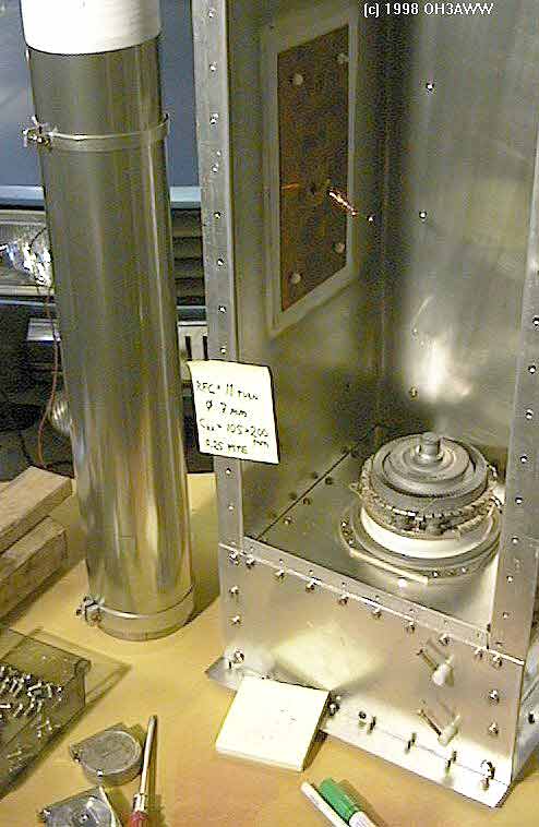
 Picture 6: Input circuit (note the non-inductive resistors in the center of the picture) |
 Picture 7: Input circuit view #2 |
Tube parameters
GU-84b and 4CX1600b maximum values are presented in the following table.
|
|
GU-84b (GY-84b) |
4CX1600b |
|
Anode voltage |
2.2 KV |
3.3 KV |
|
Anode current |
2.0 A |
1.4 A |
|
Anode dissipation |
2.5 KW |
1.6 KW |
|
Frequency |
250 MHz |
250 MHz |
|
Screen grid G2 |
400 V |
350 V |
|
Grid G1 |
-150 V |
-150 V |
|
G2 dissipation |
30 W |
20 W |
|
G1 dissipation |
1 W |
0.1 W |
|
Filament voltage |
27 V |
12.6 V |
|
Filament current |
3.7 A (3.4-4.0) |
4.4 A |
|
Filament/cathode warm-up time |
3 min |
2.5 min |
|
G1 Cin |
102.5 pF (90-115) |
86 pF |
|
Anode Cout |
20.5 pF (18-23) |
12 pF |
|
Cgp |
0.2 pF |
0.15 pF |
|
Transconductance |
71 mA/V (50-92) |
50 mA/V |
|
Anode diameter |
98 mm |
86 mm |
|
Anode temperature |
200 °C |
250 °C |
|
Air flow 1600W (flow/pressure H2O) |
1.6 mł/min, 30 mm |
1.0 mł/min, 10 mm |
|
Length |
111 mm |
109 mm |
|
Weight |
1.4 kg |
0.75 kg |
Circuit diagram
|
C1 |
5-60pF, Input load |
|
C2 |
5-60pF, Input tune |
|
C3, C5, C6 |
1nF, feed-through |
|
C4 |
1nF, DC block |
|
C7 |
40nF, G2 built in the socket |
|
C8 |
1nF, HV capacitor, inside the anode cabinet Cu/PTFE 105 x 200 mm |
|
C9 |
Output tune, Ć 68 mm 3 mm Al disk (dimensions not critical, larger OK) |
|
C10 |
Output load, Ć 55 mm 3 mm Al disk (dimensions not critical) |
|
C11 |
1nF feed-through 400V (or homebrew 0.8 mm PCB 100x200 mm) |
|
L1 |
Input resonator, 32 x 70 mm, 0.5 mm Cu |
|
L2 |
Output resonator, length 600 mm (+/- 10 mm) , Ć 100 mm Al tube |
|
L3 |
Bias choke, 10 turns Ć 5 mm |
|
L4 |
HV choke, 11 turns Ć 7 mm |
|
L5 |
VK200 choke |
|
L6 |
Round ferrite choke, 3 turns (bifillar winding) |
|
R1 |
50W 4W |
|
R2 |
2kW, low inductance 10W |
|
R3 |
25W 40W low inductance, 2.5KV (optional; protects tube during flash over) |
|
R4 |
50W 10W low inductance, 2.5KV (optional). |
Amplifier mechanical dimensions
Picture 8: PA cabinet dimensions
Tuning
The tuning of output and input circuit is not always easy task. Here are some hints and advices I got from Leif SM5BSZ. Please reserve enough time and patience for the tuning job.
Output Circuit Tuning
|
You will need a DIP-meter, SWR-meter, 2m FM RIG, 50W terminator
and 2KW non-inductive resistor. 2000W
resistor is used for simulating the tube plate impedance with normal operating conditions:
(2KV @ 1A).
|
|
| · |
Connect the tube to its socket and anode resonator to the tube. Do not connect
any voltages.
|
| · |
Adjust the tune and load capacitors to 70% from ground (30 % from resonator).
|
| · |
Connect the 50W terminator to the output RF-connector.
|
| · |
Connect 2KW resistor between anode and ground near the
tube socket.
|
| · |
Mount the front panel temporary but leave small gab near HV choke (current maximum
point). You need two panel and few glue press to do this easily.
|
| · |
Measure the resonance frequency with DIP meter via the front panel gab and cut the
length of anode resonator if necessary. DIP meter is used until you reach the FM
transmitter frequency area.
|
| · |
Connect the SWR-meter to PA out connector and adjust the SWR to minimum with load
and tune.
|
| · |
There is possibility that anode resonator length is not correct or that tune/load
capacitor disk is too small.
|
| · |
The real dimensions are checked only with all tube voltages on. So I recommend leave
the anode a little bit long before correct length is known for sure.
|
| · |
If on normal operation conditions G2 goes negative, then output load is too small.
Move load closer to the anode line and adjust tune to max output power (farther of
anode). I tune G2 current to 20-30mA. If you can’t do this then anode line is too
long.
|
Input Circuit Tuning
|
The input circuit was a little bit complicated to tune than output. Jerry W9QXP uses
50W resistor input that needs no tuning at all. I did try
this but with poor result. I couln’t get more than 600W output with 100W drive. I
decided to use a traditional LC-circuit. Here are some hints how to pre-tune it.
|
|
| · |
Install the tube and connect blower and filament on. Note: disconnect all other wires.
Connect 8KW resistor between G1 and ground. This resistor
simulates normal operation conditions: 90V @ 11mA.
|
| · |
Use a multimeter to measure DC voltage between G1 and ground over the 8 kW resistor.
|
| · |
After 3 minutes heating time connect
drive for 144 MHz and change tune and load so that there is maximum voltage in
G1. The tube works as a diode and rectifies all RF. Do not touch to anode or G2
because there are very high voltages.
|
| · |
Input SWR should also be near 1 at the G1 voltage peak settings. The maximum needed
80V is reached with drive level 30 - 40W.
|
| · |
Finally the input adjustment is made with normal working conditions with SWR meter.
After this there is usually no need to change input tune or load capacitor values.
|
| Finally | |
|
This amplifier has been in use since June 1997. There has been no problem with
it. In my mind the construction is simple, even though it uses a lot of aluminium.
I can recommend this project without any reservations.
|
|