GU43b tetrode HF Final specifications:
Pout > 1000 W
Pin < 20 W
Power consumption <2500 W
In/out RF impedance 75 ohm
3rd order intermodulation distortion -30 dB
SWR in input circuit < 1.5
Gain 17db
TV2 Filament transformer 12.6 V AC, 100W.
TV1 17 bifilar turns on 4 cores M200HH 32*20*6 mm, 1:1 transformer.
GU43b's Cin is 100 pF, for its compensation L1 and TV1 were used.
SWRin is less than 1.5 on 28 MHz and less than 1.2 on other bands.
VD14+FU3+C28 - protection from HV pulses.
FV1 slow HV pulse protection (gap).
R4 reduces dinatrone effect, it influences to the central position of PA1.
K3 works faster than K2 and K6.
TV3 63 W transformer.
M1 blower for radiator, 180m3/hour.
M2 blower for cathode part, 100 m3 /hour.
PA1 1 mA.
C1,3,4 10 kV.
C7 K15Y-1 4kV, 15 kVar.
C9 HV var capacitor with 3 mm distance.
C10-C22 are integrated with original GU43b socket.
C5 1 kV ceramic.
SA1 220V 15A.
FU3 HV fuse 1A.
TV1 HV transformer with 0.75 mm diam wire for the secondary.
VL1 GU43b, installed horizontaly.
VT1 KT839A HV transisor.
DA1 KR142EH9 24 V .
R4 20 W .
R2 9 pieces of 2W 75 ohm resistors.
VD2-VD13, VD16-VD18, VD30,VD33 - KD226D (1.7A@800V).
VD19-VD27 5W Zenner diodes D816D (47V@110 mA).
VD28 5W Zenner diode D817b (68V@75 mA).
TA1 Primary - direct wire inside of core, secondary - 2-4 turns.
L1 5 turns, 1 mm diam wire on 10 mm diam ceramic, step 1 mm between turns.
L2 Plate choke, 0.5 mm enemaled wire on ceramic 30 mm diam.There are 4 sections.
1st-11 turns with step 1.5-2 mm; 2nd-14 turns; 3rd- 21 turns; 4th - 70 turns.
Distances between sections are 5 mm.
L3 28 MHz coil, copper tube 6.5 mm diam, 5 turns with inside diam of 50 mm.
Tap is 4 turns from hot end.
L4 21/14 MHz coil, copper strip 5*2 mm, 6.3 turns with inside diam of 50 mm.
Taps are 2.2 and 5 turns from L3.
L5 7/3.5 MHz coil , 17 turns of 3mm diam copper wire on ceramic 50 mm diam.
tap is 7 turns from L4. Step 2 mm.
Step for L3 and L4 is equal to diam of tube ( width of strip).
R3 ajusts current via VD28 -10 mA.
R6 ajusts current via VD19-27 -20 mA.
R4 installing grid current "Zero" on PA1.
C40 - delay for K7.
Ufil with inserted tube must be 11.6- 13.5 V AC.
With 5 W drive, it is necessary adjust for min SWR-in on 10 m band with L1.
How to switch on this final:
1. SA1 on and wait 5 minutes;
2.SA2 on;
3.SA2 to position 2 and after 2 sec to position 3;
4. SA3 on.
R13 ajusts Ir 250-300 mA.
Screen current for GS43b must be less than 80 mA, opthimal is 15-25 mA.
Similar final is described at:
ARRL Handbook 2000, The Sunnyvale/ Saint Petersburg Kilowatt Plus. 13.29
|
Click on pictures to enlarge
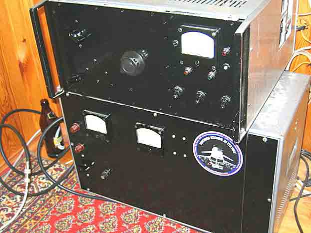
Front Panels
|
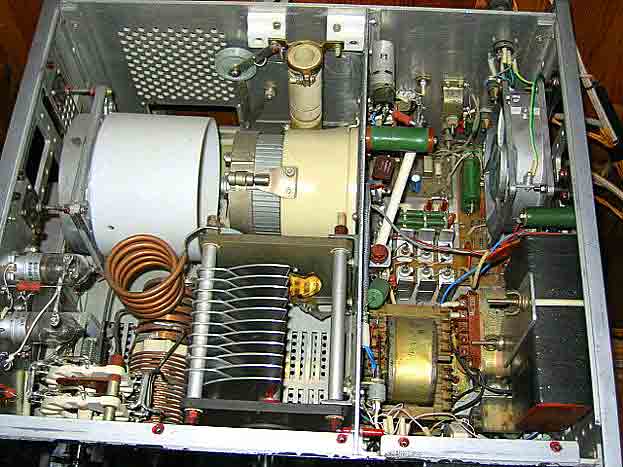
Top View
|
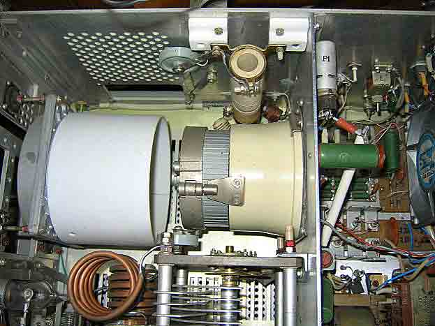
GU-43B Installed
|
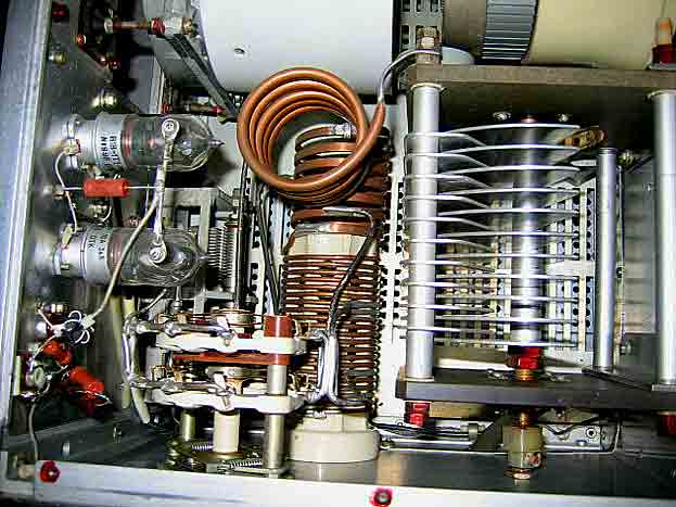
Pi Network
|
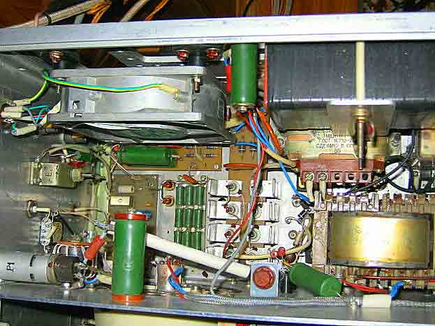
Non-RF Circuitry
|
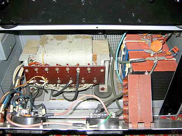
Power Supply
|
|