Single GS-15B PA
|
Single GS-15B PA insulators
|
|
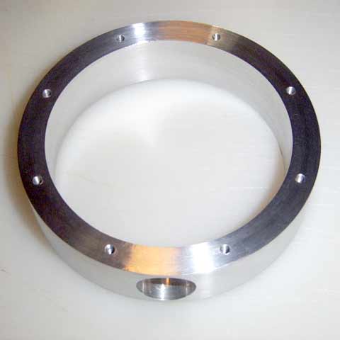
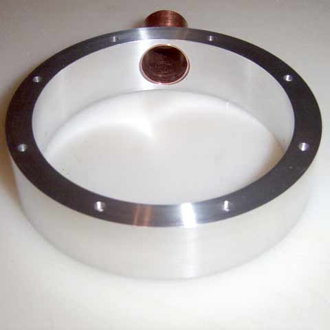
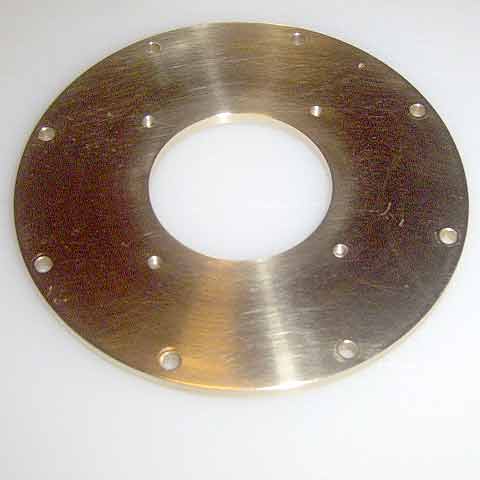
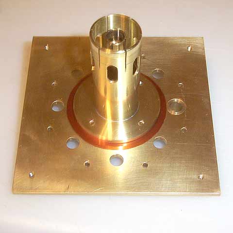
Anode Cavity
Top Plate
|
Dimensions:
OD = 94mm - (3.700”) - (Not critical)
Thickness = 3.2mm - (0.125”)
Center hole = 38mm - (1.500”)
Plate ring holes circle = 51mm - (2.000”)
Mounting holes = 3.2mm - (0.125”)
Plate ring threads = M3 - (Not critical)
|
|
|
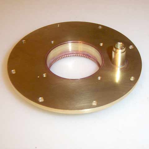
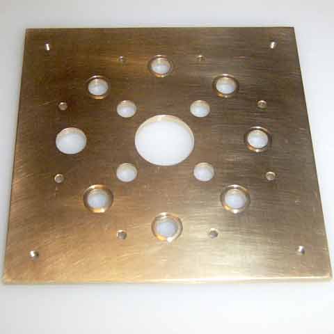
Anode Cavity
Bottom Plate
|
Dimensions:
OD = 94mm - (3.700”) - (Not critical)
Thickness = 3.2mm - (0.125”)
Center hole = 42mm - (1.654”)
Grid ring hole circle = 51mm - (2.000”)
Mounting holes = 3.2mm - (0.125”)
Grid ring threads = M3 - (Not critical)
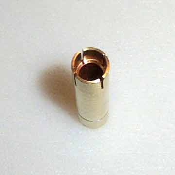
The tuner sleeve is made from a ˝” long - 3/8” diameter brass rod that is drilled and tapped Ľ”
- 20. Solder the sleeve in place and keep it flush with the inside surface of the cavity.
|
|
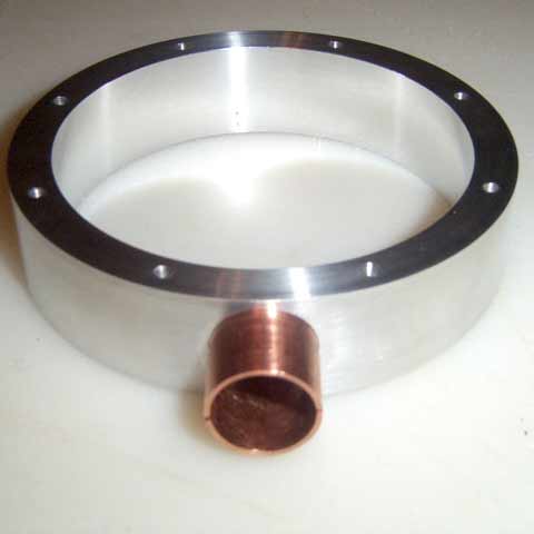
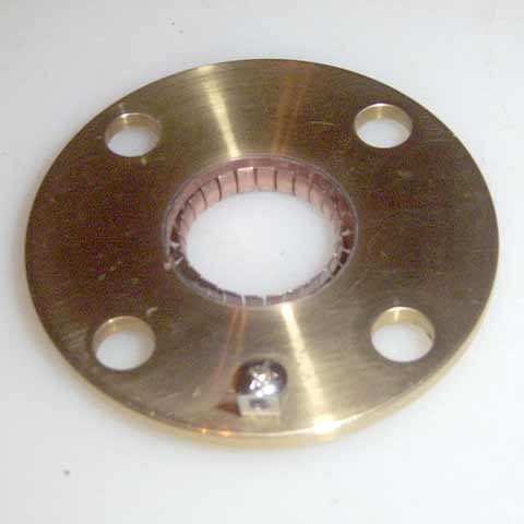
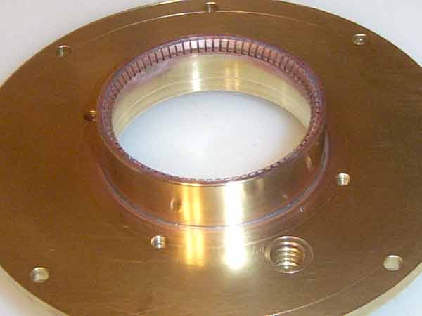
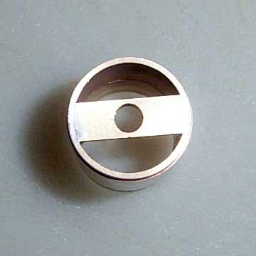
Screen Ring
Anode Cavity
Bottom Plate
|
Dimensions:
Height = 13.8mm - (0.543”)
OD = 42mm - (1.654”)
ID = 39.5mm - (1.556”)
Solder the finger-stock in the top of the sleeve. Solder the sleeve to the bottom plate.
The ring should be flush with the bottom side and extend upward into the anode cavity.
|
|
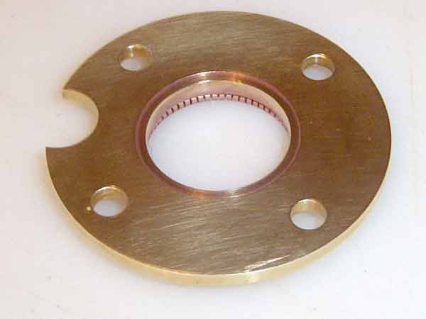
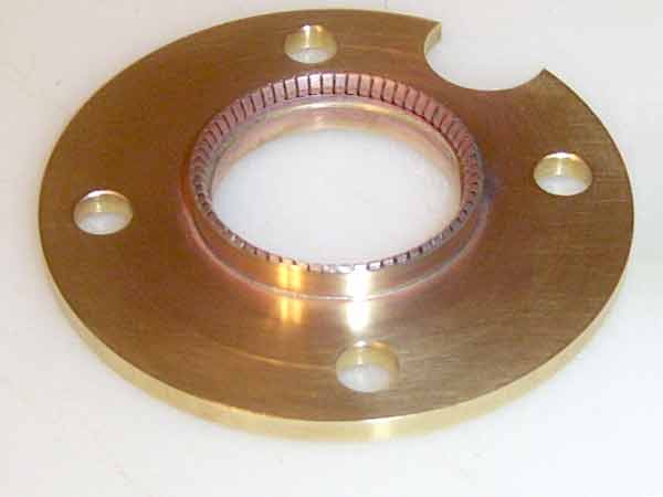
Grid Ring
|
|
|
Grid Sleeve
|
Dimensions:
OD = 32mm - (1.260”)
ID top 4mm = 31mm - (1.220”)
ID bottom 4mm = 27mm - (1.063”)
Height = 8mm - (0.316”)
The sleeve has a step 4mm from the bottom to act as a mechanical stop for the tube socket.
Solder the finger-stock in the top (larger end) of the sleeve and solder the sleeve to the
grid de-coupling ring, flush with the bottom of the ring.
|
|
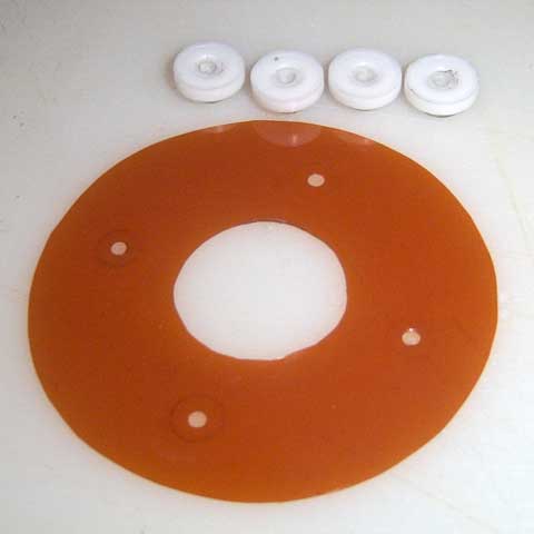
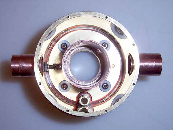
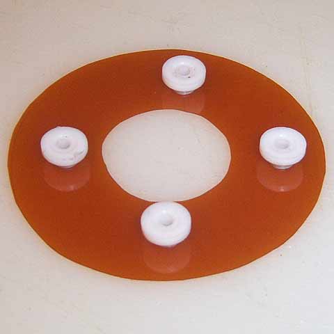
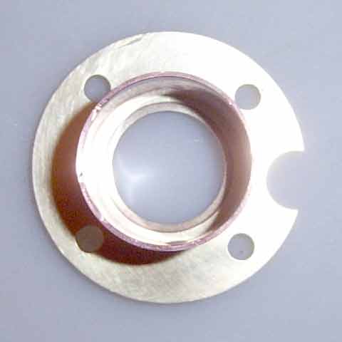
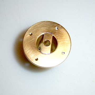
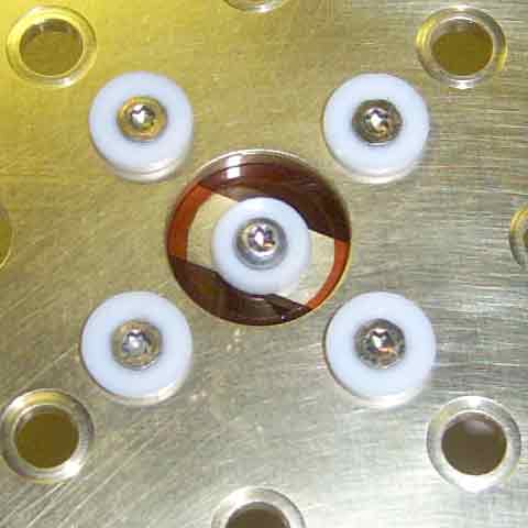
Grid decoupling
capacitor Insulators
|
The kapton dielectric and teflon hardware insulation used to install
the grid ring/sleeve & input resonator assembly to the bottom of the anode cavity.
|
|
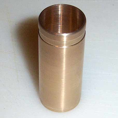
Input Resonator
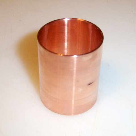
|
Dimensions:
OD = 37.5mm - (1.478”)
ID = 35mm - (1.380”)
Length = 46mm - (1.810”)
The resonator is made from a standard 1-1/4” copper pipe coupler, available in any hardware
store.
|
|
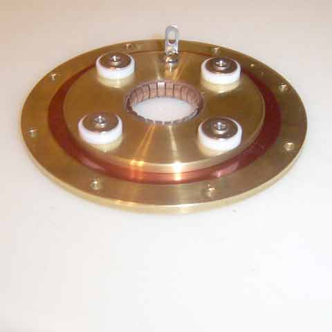
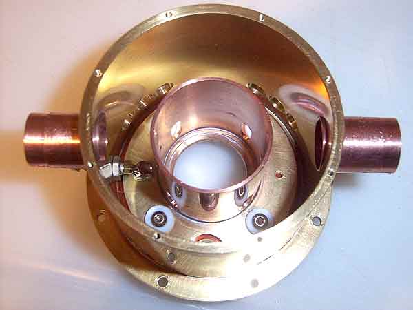
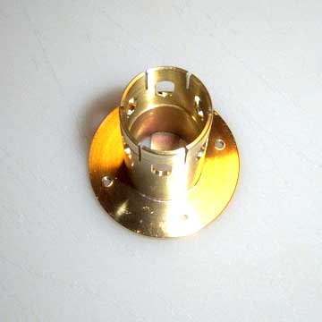
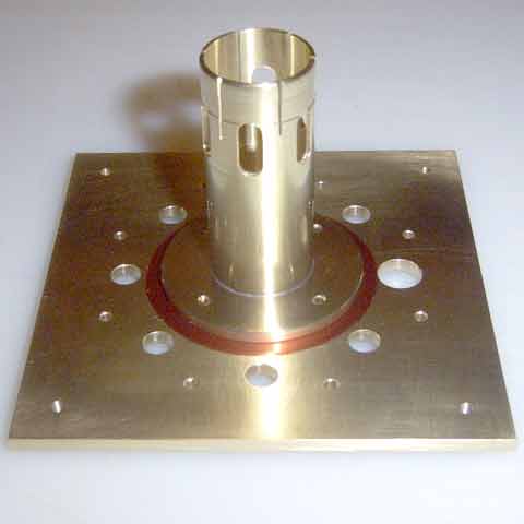
Input Resonator
Assembly
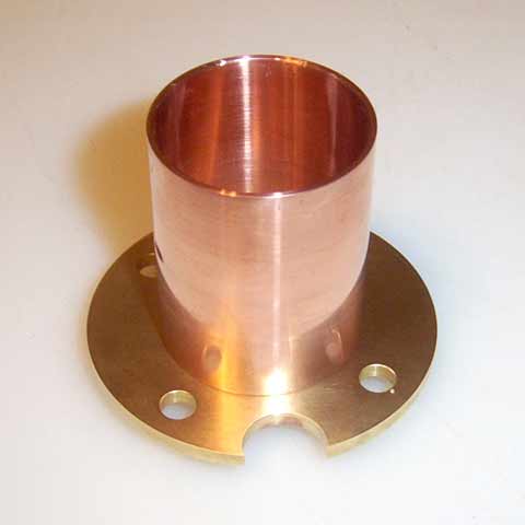
|
Center the input resonator on bottom side of the grid ring and solder in place. Drill a
few Ľ” holes in the resonator, close to the grid ring, to allow for air circulation.
|
|
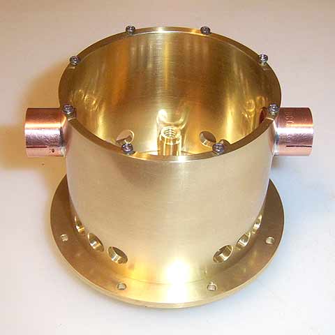
Input Cavity
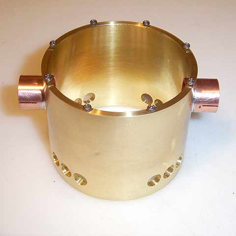
|
Dimensions:
OD = 75mm - (3.000”)
ID = 70mm - (2.750”)
Length = 60mm - (2.360”)
- The input cavity is standard 3” brass tubing with 1/8” wall.
- Drill 8-12 holes, 1/4" - 5/16" diameter, close to the plate cavity end to promote air-flow.
- Input coupler and tuner sleeves are the same as the plate cavity output coupler.
- The centers of the sleeves are located 40mm (1.575”) from the plate cavity end.
- Push these through the wall and solder in place.
- Drill and tap 8 - M2 holes for mounting of the bottom plate.
- Drill a hole 10mm (0.400”) from the plate cavity end. This hole is for a grid voltage
feed through capacitor.
|
|
|
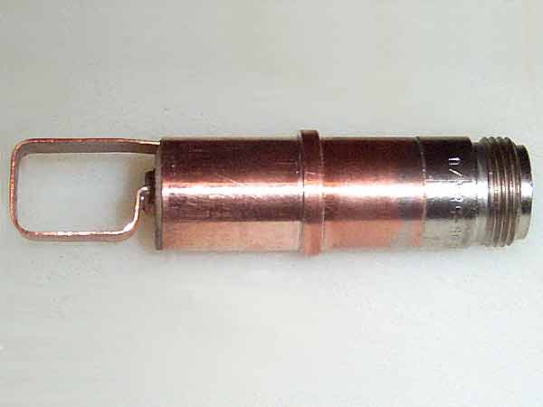
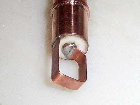
Input Coupler
|
The coupler is fabricated from a piece of ˝” copper pipe (0.625” OD) with a Ľ” brass rod as
center conductor. The disc in the end is a 15mm (0.600”) brass washer. Glue a piece of Kapton
or Teflon sheet to the end of the disc to prevent accidental short between ground on grid.
|
|
Input Tuner
|
The input tuner is fabricated from a 2-1/2” long Ľ”-20 brass screw with a 15mm (0.600”) brass
washer in the end. The holder is fabricated from a piece of 5/8” copper or brass rod.
The holder is threaded in the disc end and hollow in the other end to allow space for a spring.
The cap is threaded in the outer end and hollow in the opposite end to slip over the holder.
This will pre-load the tuner threads and give a smooth tuning. Glue a piece of Kapton or Teflon
sheet to the end of the disc to prevent any short between ground on grid.
|
|
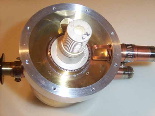
Input Cavity
Tuner & Coupler
Installation
|
Install the input coupler and tuner and secure with #6 hose clamps. Initial setting is about 4mm
from the input resonator for both the coupler and tuner.
|
|
|
Cathode Resonator
|
The cathode resonator is made from a 55mm (2.170”) length of 1” brass tubing machined down to
22.65mm (0.8915”). Cut 6 - 20mm (0.75”) long slots from the tube end to allow for compression.
Drill 6 holes, 6mm (1/4”) diameter to promote air-flow. See Cathode decoupling explaination, below.
Install an 8mm wide brass strip across the bottom of the resonator, outside surface flush with
end of tubing. Solder in place. Drill a 4.5mm hole in the center for heater connector mounting.
|
|
Cathode Resonator
& Decoupler
|
|
|
Heater Connector
|
The heater connector is made from a 50mm (1.9675”) length of 9mm (0.350”) brass tubing.
The tube end is drilled to 7.8mm (0.3075”) inside diameter, 10mm depth (0.400”). Cut 4
slots - 15mm (0.600”) long to allow for expansion when pushed on the tube.
Solder an M3 nut inside the tube in the opposite end. This will be used for mounting.
See "Cathode Resonator Assy & installation", below.
|
|
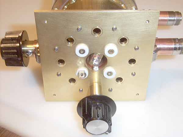
Input Cavity
Bottom Plate
|
Dimensions.
OD = 94mm - (3.700”) - (Not critical, round or square OK)
Thickness = 3.2mm - (0.125”)
Center hole = 20mm - (0.750”)
Resonator ring holes circle 35mm - (1.375”)
Resonator mounting holes 6.2mm - (1/4’)
Plate mounting holes 2.2mm - (0.085”)
Cooling holes circle 62mm - (2.450”)
Cooling holes diameter 6.2mm - (1/4”)
Plate tuner hole 9mm - (0.350”)
The center hole is for access to the heater terminal. The holes on the inner circle are for
mounting the cathode resonator. The next circle of holes is ventilation. The outer circle
holes are for mounting to the input cavity.
The larger hole on the left side is for the plate tuner. The 4 corner holes are for mounting
the finished amp.
|
|
Cathode Resonator
assy & installation
|
- Mount the completed cathode resonator to the bottom plate with Kapton insulator on the
inside and Teflon shoulder insulators on the outside. Cut the Kapton insulator > 2mm
oversize to prevent arcing. Voltage across these surfaces will be 350-400V.
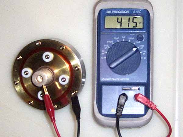
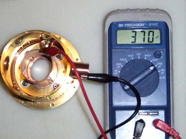
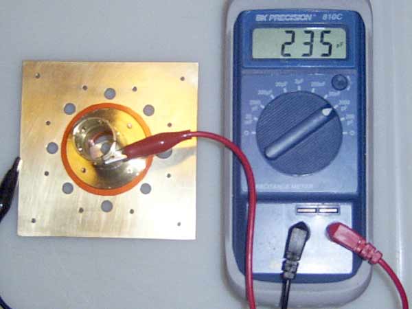
- Second picture shows the value of the input resonator decoupling capacitor in pF.
- Install the heater connector inside the cathode resonator with insulators on all sides.
The differential voltage between the cathode resonator and heater tube is only 6VAC so
arcing is not an issue.
- Put a spring and nut on the output tuner screw to pre-load the threads and get smooth
tuning.
Mount a solder eyelet to the heater screw and one of the cathode resonator screws.
|
|
Top View
|
Side View
|
|
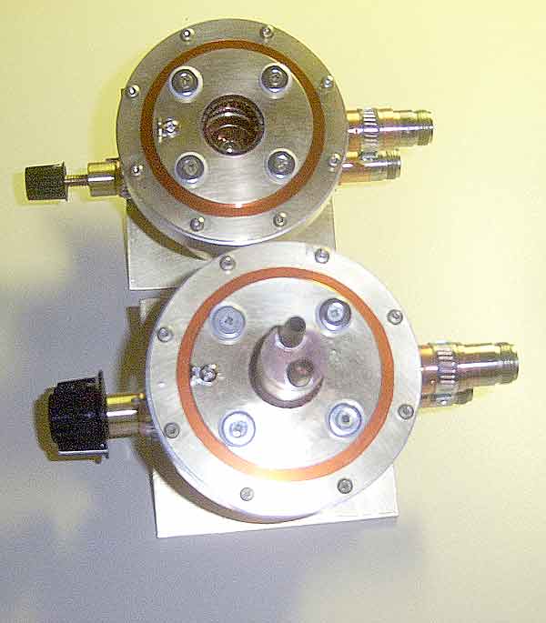
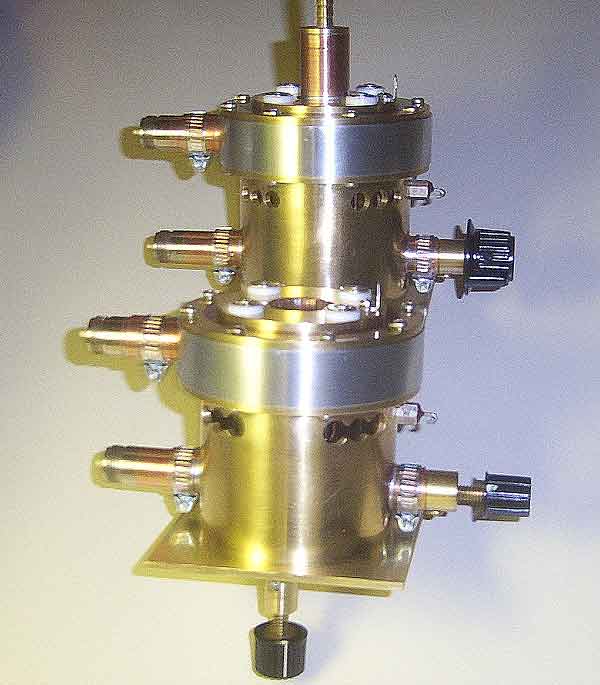
Two PAs, one with tube installed, made following the details shown above. Proof of the
pudding, so to speak!!
|
|