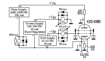
GS-15B single tube 300W grounded screen 23cm PA
| Operational Parameters |
| Parameter |
Totally stable to 250-300W output |
Up to 400W out with Minor
thermal drift (class B or C) |
| Anode voltage |
1600 - 1800 Vdc |
2200 - 2300 Vdc |
| Anode current |
<350mA |
<325mA |
| Screen voltage |
320 - 350 Vdc |
350 Vdc |
| Screen current |
+ 1 to -1mA when tuned correctly |
+ 1 to -1mA when tuned correctly |
| Grid voltage |
-22 to -32 Vdc |
-30 to -40 Vdc |
| Grid current |
5-20mA |
8-15mA |
| Idle current |
50-75mA |
0mA |
| Heater voltage |
5.5 - 5.8 VAC |
5.5 - 5.8 VAC |
| Drive power |
10W |
15W |
| Typical efficiency |
50% |
>55% |
A Few Warnings
Since this tube is generating negative screen current, it will self-supply screen voltage.
There MUST be a resistor of <100KOhm between ground and cathode at all times to bleed off
self-generated screen voltage.
NEVER switch the screen voltage on and off without this resistor in place to bleed
off the screen voltage.
Disconnecting the screen with anode voltage present and no load resistance WILL cause
a failure. The result is that the screen voltage will increase up to the anode voltage
potential and cause an arc-over in the grid de-coupling insulator or internal arc in the tube.
The screen power supply must be of shunt type to prevent a screen voltage increase
when the amplifier is tuned in-correctly, or you could get an anode current run-away. It
is also recommended to use a sensing circuit to trip to amp if the screen current goes more
that 5-10 mA negative.
Additionally, a 100 ohm, 50W resistor is inserted in the anode supply line to act as a
current limiter in case of a flash-over.
Tuning:
Keep eyes on the screen current while tuning the PA. The screen current will go drastically
negative (-15mA) if the cavity is tuned too low in frequency.
Apply 5-10W drive and tune the output for maximum power by alternately adjust the anode tuner
and rotate the output coupling loop. Tune the input cavity for best SWR by alternately rotate
the tuner and adjust the input coupler in and out.
Re-adjust the output for maximum power. Watch the screen current and adjust the anode tuner
slowly CW until you see a decrease of about 1mA (negative current). You should now be about
10W below maximum power. This will ensure that the amp will reach full power immediately
after an idle period.
Cooling:
Use a distilled-water cooling-system with good flow rate. It should be able to handle >300W
load without over-heating. It is recommended to use a small quiet muffin-fan to blow on the
input cavity. The amp is generating very little heat so a low capacity fan is sufficient.
Heater voltage:
Too high heater voltage will drastically shorten the tube life.
Recommended fine-tuning:
- Run the heater on 6 volts for 10 minutes or more.
- Drive the amp to 100-200W output.
- Lower the heater voltage in 0.1V steps until the output starts to drop. Wait a few
minutes between each step. This typically happens at 5.4 to 5.8 volt.
- Increase the heater voltage to 0.2 volt above the point where the output power drops.
This is done to minimize any cathode back-heating. Tests have shown that most tubes have full
emission down to 5.4 volts. Higher heater voltage than necessary will only shorten the tube
life with NO power gain.
Leave the heater on for at least 2 minutes before transmitting to allow the cathode surface
to reach uniform temperature.
Tube replacement:
The cavity top has to be removed to replace the tube.
- Remove the 8 outer screws.
- Pull off the top plate.
- Pull out the tube.
- Install the new tube. Push down until it bottoms out.
- Push the top plate in place. The plate has a hole to match a roll-pin in the cavity.
- Install all screws.
- Re-tune the cavity to match the new tube.
Rf-Chokes:
All de-coupling is done inside the amp and no external rf-chokes are needed.
RF-Leaks:
The cavity’s RF leaks are almost zero so no extra shielding is needed for this reason.
You are working with lethal voltages, so install in a cabinet or other place where the high
voltage can not be reached.
Good luck
