|
Water Cooling the GS-3A by KD5FZX Click on callsign for e-mail |
|
Manufacturing a GS-3A water cooling jacket
|
GS-3A with no cooler installed.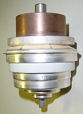 |
||||
| Click on pictures below for zoom | ||||
|
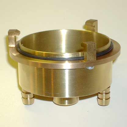
The GS-3A is intended for water cooling. To the left, a water is jacket installed on the tube, clamped and ready for service. At the right is a cross-sectional drawing showing the tube and water jacket as installed; note that there are TWO seals, a rubber O-ring and a teflon gasket upon which the bottom of the water jacket seats. |
|
||
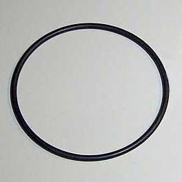 |
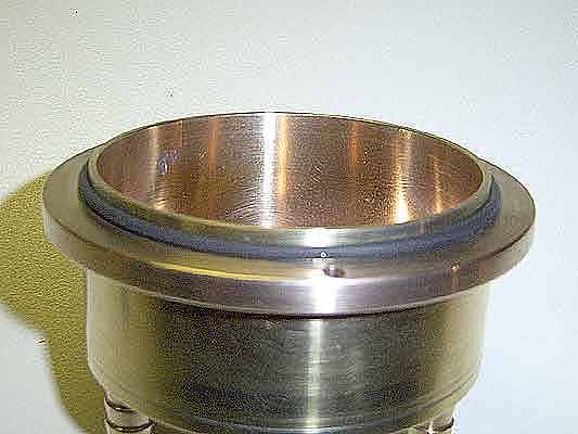
At left: the O-ring (2.75” O/D with 1/8” thickness). |
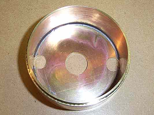   |
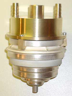
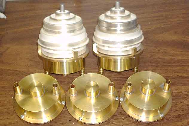
Inside view of the water jacket & top plate ass'y.
|
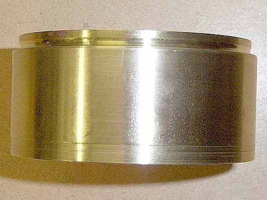
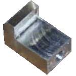
The cooling jacket is fabricated from a 3” O/D brass tube with 1/8” wall thickness. Tube
length is 33mm (1.300”). The diameter of the jacket seat area (where the bottom gasket is
installed) on the GS-3A tube is 73.5mm (2.894”). The bottom of the brass tube jacket is
machined to 73.4mm (2.890”) to fit inside the seating area (which is 4.2mm (0.165”) deep).
The machined length at the bottom of the tube is 5.4mm (0.212’) to allow for a gasket and
O-ring. A groove was machined for the O-Ring (see picture). This is not absolutely necessary
since the O-Ring will be clamped in place during installation.
|
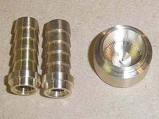 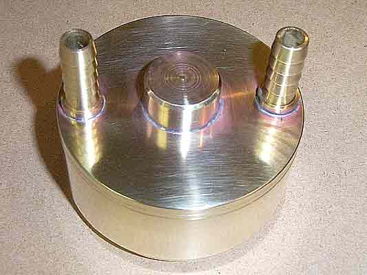  |
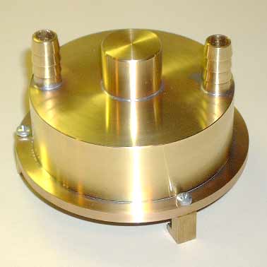
Hose-barb water connections and top cap before installation in the cooler top plate.
|
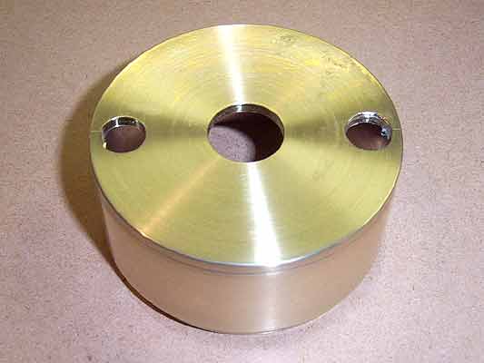
The treaded end of two standard 3/8” brass hose-barbs with Ľ” NPT is machined to 3/8” O/D to
match the outer holes in the top plate of the cooler assembly.
|
|
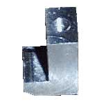   |
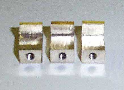
The clips are machined from brass stock. See drawing below. |
 |
INSTRUCTIONS: |
|||
|
At left is the completed water jacket ready for installation.
|
|
|
|
|
Description & pictures of a water cooling system. |
go to the top
|
Best Viewed: MSIE 4.0 & higher, or Netscape 3.02 & higher, and screen set to 800x600 pixels This Page Last Updated: 17 May 2004 Feedback: Paul S. Goble, III, ND2X Copyright © 2003 -2004 by ND2X and KD5FZX, all rights reserved |