by
KD5HIO
|
Construction Details
The pictures below show details of various parts of the construction project.
|
| Loading and Tuning Capacitor construction | ||||
|
|
|

|
|
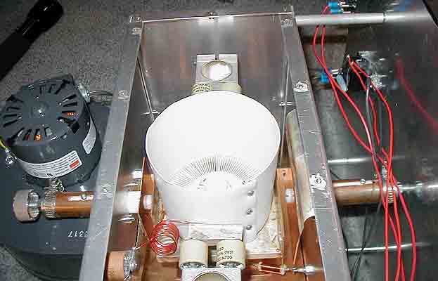
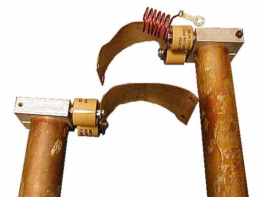
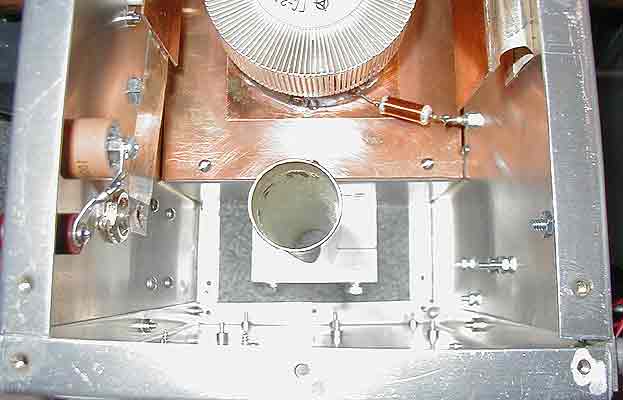
The load and tune capacitors, along with the mechanical apparatus that change the plate
spacing, are shown in the color diagrams. The tune capacitor is built from 0.064" copper
plates, 4" X 2.5" in size. The load capacitor uses square plates 1.5" on a side. The
mechanical screw adjustment facility is designed to vary the spacing between the plates
from about a minimum of 1/4" to a maximum of 3/4", with the spacing varied by turning
the tune knob on the front panel. The plate nearest the front is fixed to ground using
a thin copper strap, the width of the plate. This overall design is not very critical,
as long as it provides sufficient minimum and maximum capacitance to handle the amplifier
in normal operation.
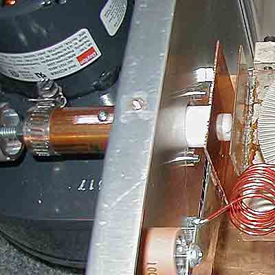
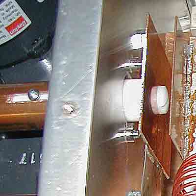
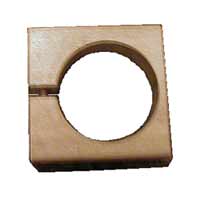
Finally, a Dremel tool is used to cut a slot lengthwise in the copper pipe, to allow a
small screw (labeled "pin" in the drawing) to be threaded into the plug to prevent the
plug from rotating as the tune knob is rotated.
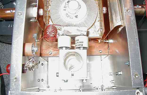
After assembly, check the operation of the capacitors. If the plates of the tune capacitor are not parallel, or they are adjusted too close, it is possible to have an HV arc between the plates. This is usually not damaging, but quite unnerving for the operator. However, if an HV arc appears on the plate load capacitor side, the center of the coax will rise to the HV potential. This is to be avoided at all costs for safety, typically by employing a shorted stub harmonic filter right at the outlet "N" connector. It is possible to have RF arcs between the movable load plate and the chassis, and right at the outlet "N" connector if the circuitry comes too close to ground. These are very hard to find, as they do not leave the black mark that appears at the site of an HV DC arc. To prevent such, the nuts on the all-thread shaft are adjusted such that, when the shaft is turned, the teflon plug slides in and out of the copper pipe to place the capacitor plate the correct distance away from the corresponding anode plate. The moveable plate should not approach the anode plate any closer than 1/4" to prevent arcs - this separation is enforced both by the setting of the nuts and by the head of the nylon screw that attaches the movable plate to the teflon plug. On the opposite extreme, the movable plate should not come any closer than 1/4" to the amplifier chassis. Thus the moveable plate has approximately 1/2" to 3/4" of useable travel which is more than adequate to load and tune the amplifier. |
| Tube Socket Construction |
|
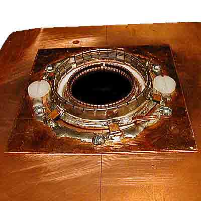
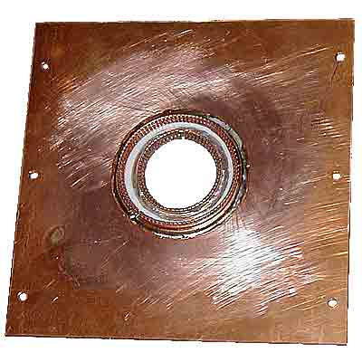
| Anode Resonator Construction | ||
|
|
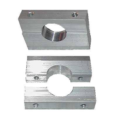
|
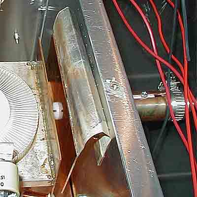
Above see the pieces of the resonator assembly; at left the top assembly, at center the top resonator clamp and at right the bottom resonator clamp. Below see (left) a resonator installed on the podest with the bottom clamp and (right) the completed resonator assembly with top clamp, DC blocking capacitors, etc. |
||
| ||
go to the top