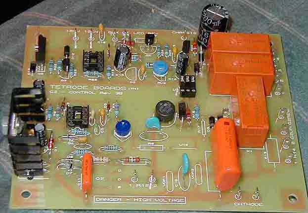
The changes detailed below are referenced to the "The Tetrode Boards
- Control and Protection for your Tetrode RF Power Amplifier." assembly
manual, version 1.16, April 2003:
On page 5 of the manual, there is a list of "What you'll need" -
1) The 0-330VAC, 100mA transformer mentioned was replaced with an
RF Parts 25-0300-02 550VCT part. The base tetrode board is a 350-400V
design, the GS-23B will operate at a G2 voltage of +600VDC (with
respect to the cathode).
2) The filament transformer used was a Mouser 553-VPS12-3400 (6.3
VAC 6.8A) with a Mouser 71-LVRS-0.015 (0.015 ohm) resistor selected
to provide 6.3 VAC to the GS-23B filament.
3) The control grid xformer used was a Mouser 553-N48X (115VAC 0.13A
isolation transformer).
4) The "relays etc" xformer was a Mouser 546-185D36 (36 VCT at 1.2A).
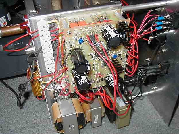
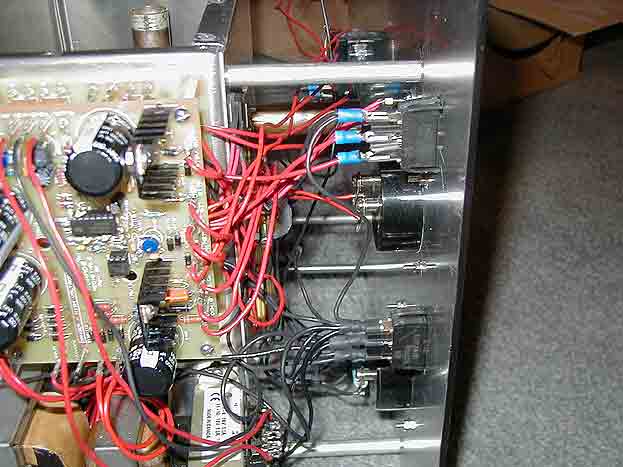
5) Q2, along with the big metal-cased resistors (R12, R14, and R1
shown on page 7), are not mounted on a separate heat sink, but
right to the metal K3IWK chassis. That chassis is air cooled with
a big blower which should be sufficient to keep these parts cool.
6) M1 and plate ammeter, RF Parts 670 (0 - 30 mA).
7) M2 RF Parts 670 (0 - 30 mA).
8) Screen cathode bleeder Mouser 284-HS50-50KF (50K 50W)
9) We are building option 3.3 on page 7, "Cathode Driven, DC-grounded Control Grid"
10) Shunt plate ammeter with a 0.08 ohm Mouser 71-LVR5-0.08 to read 1.2A full-scale.
11) Item 9. Replace Q2 with a Mouser 511-STW11NB80 (or equiv) due to the higher screen
voltage.
12) Page 10, item 10. Replace R12 with a Mouser 284-HS100-5KF (5K 100W), R14 with a Mouser
284-HS15-330F (330 ohm 15W).
13) Page 11, topic 5.1.2. Build the second option, "Energized on
receive", if that is appropriate for your station.
14) I enabled TX Inhibit, the design does not need G1 switching.
TX inhibit will not be used initially, but it is enabled in case
one chooses to use it sometime in the future.
15) Page 12. I use 12 V relays only, so I built that option.
16) I use HV supply control to energize the relay in the HVPS that
starts the supply timer going. This signal is isolated with a simple
SPST relay.
17) One does not need G1 switching, bypass R107 with wire link as suggested.
18) Page 13, item 5.5. I don't use ALC, but read this if you are
interested. I don't use AUX TRIP IN either, but one could failsafe
the blower here if wanted.
19) I assembled the chassis, and all possible attachments, using the
Mouser 532-1560B swaged standoffs as captive nuts.
20) More component substitutions:
a) R10 is replaced with 270K ohms 2W total resistance (Mouser 281-150K and 281-120K in series).
b) R8 + LNK are replaced with Mouser 281-390K (780K total resistance).
c) all varisistors are replaced with Mouser 570-V480LA80B, due to the higher G2 voltage
d) replace D6 with a 12V zener (1NT4742A or equiv) if it is a 4.7V zener in your
kit (this substitution provides more robust operation of the screen grid voltage regulator).
e) D114 needs to be the 47V 1N5368B as 47V G1 bias is needed for the GS-23B.
f) eliminate RV102; jumper REC-G1-ALC board pins CW, SL, and CCW together (original
design has too much resistance between R104 and R106 to supply good regulation for
the GS-23B which may draw up to 30mA of G1 current in CW/FSK modes).
g) Page 8, RFC1 is shown as 40 turns on a 100 ohm 1W resistor. 10 turns of #16-#18
are more appropriate for the 2M design.
|