|
Neutralization of GI-7b / GI-7bT 23cm Amplifiers
It is well known that 23cm PAs using Russian GI7b / GI7bt tubes suffer from thermal drift
and can oscillate under certain conditions. The majority of amateur radio designs using
these tubes are based on 3/4 lambda cavities, the famous
CT1DMK design being the prime example. These
amplifiers commonly exhibit thermal instability and low efficiency. Instability may also
cause the PA to oscillate or, at minimum, create bad intermodulation distortion on the
output. This creates splatter which is especially problematic during contests, particularly
if many stations are active.
The GI7b / GI7bt tube is not the best tube for linear amplification on the 1296MHz band,
but because these tubes are relatively cheap and accessible, many of us tried to use them.
Based on the characteristics of the tube, one should not expect PA output power higher than
200 - 250W for ordinary operation, with efficiency no higher than 35%, even with very well
made and silver-plated cavity. Thermal instability is a constant problem.
Where is source of instability? One part of it is well described by KD5FZX here. The second part, which is the primary
cause at lower output levels, is due to the positive feedback inside tube from parasitic
energy transfer between anode and cathode. This feedback can increase gain of amplifier
and lower attenuation of input reflections of the amplifier. The result is that input
matching varies with anode cavity tuning. When anode cavity is detuned by thermal drift,
feedback to the cathode decreases and rapidly lowers aplifier gain. This results in much
lower output power even if input power is stable.
How to test your amplifier:
Now you should to try neutralize your amplifier:
- Neutralization is accomplished by increasing inductance between the grid
of the tube and ground. It creates a resonant circuit with Cag & Cgc which
couples anode voltage to the cathode shifted in phase; it is 180 degrees out of
phase with parasitic transfer of energy through Cac. This phase shifted
transfer reduces positive feedback to the point where oscillation no longer
occurs.
- Theoreticaly it is simple - because of small variations in construction of
different cavities, however, there are differences in inductance and capacitance
which can complicate the neutralization process. With this in mind, VE4MA developed
a reliable method which is shown here.
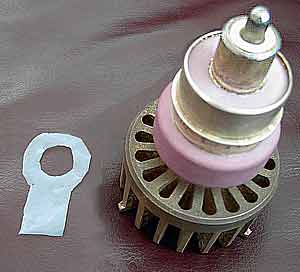
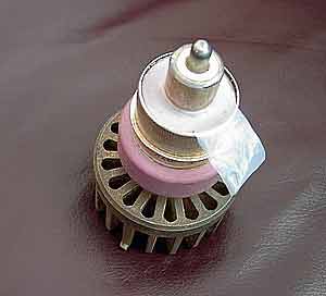
It causes a small increase of grid holder inductance by isolating part of the grid ring
from the grid contacts.
I have tested many tubes in different cavity arrangements and can recommend the
solution below which is illustrated in the pictures.
- Put a teflon (or paper for test purposes only) strip as shown, width aprox. 24mm, on
the tube, install the tube in the cavity and measure feedback transfer as described in
point four above. Feedback should be 13 to 16 dB or a bit better (more dB). If
not, pull out the tube and change width of strip to 22mm and repeat. For different
tubes and grid holders is usually possible find proper strip width to increase feedback
attenuation to at least 26 dB.
- Next, rotate the tube in steps of 15 degrees or so. Remember to be careful of the
HV on the anode! Because grid inside the tube is not absolutely symmetric, you will
probably be able find a feedback minimum - at least 30 dB. Make this position of
tube and teflon strip permanent.
- Connect a load to the output and switch the amplifier on. Test the input SWR.
Although anode cavity tuning will still have an influence on the input SWR, attenuation of
reflection on the input should be now at least 18-20dB for any adjustment of anode cavity
tuning. Do not readjust cathode from setting achieved above.
- Test gain of amplifier with low output now - maximum gain, after peaking output with anode
cavity tuning and loading, should be between 10 and 12 dB.
Results:
- Your amplifier will have a bit lower gain than before, but will be much more stable. You
will need to use higher driving power.
- Because of much lower feedback, you will be able probably setup lower loading of anode
cavity and by this way obtain a bit better efficiency without danger of oscillations.
DO NOT FORGET to be careful with HV on the anode!! Best regards and many successfull QSOs on 23cm.
Vladimir OK1VPZ
www.qsl.net/ok2kkw
|