|
THE PA3CEG 23 CM GS35b PA Parts |
|
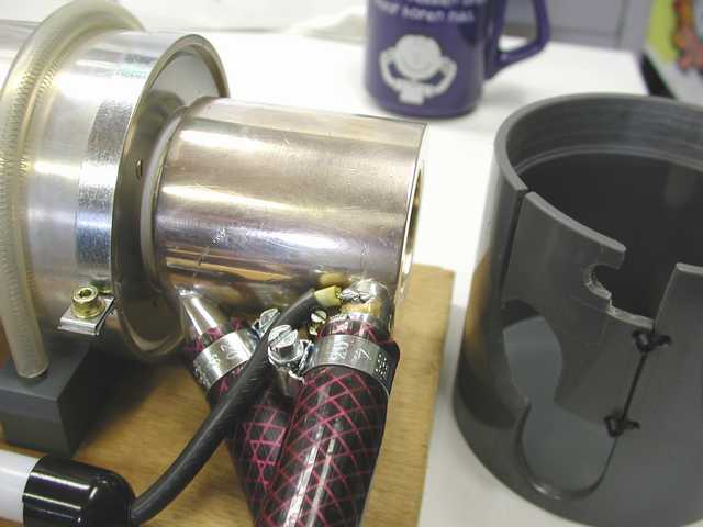
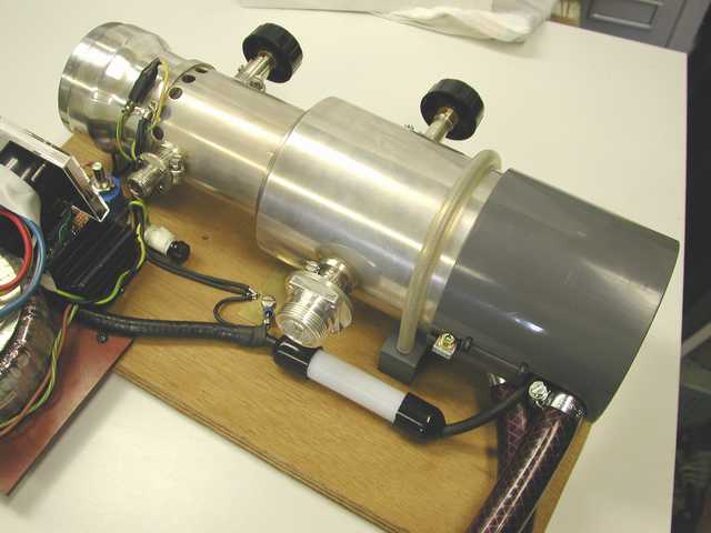
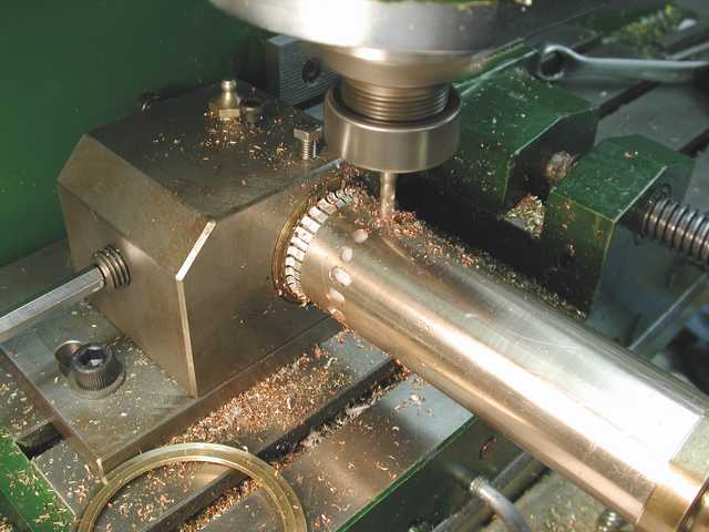
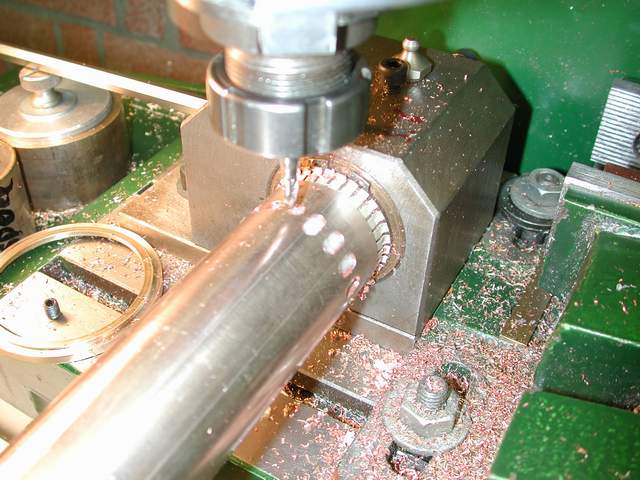
Safety first, so all the HSP parts were masked with Teflon or PVC covers. |
 23cM-GS35-cool7.JPG |
 23cM-GS35-compl4.JPG |
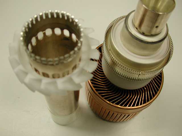
Air is forced through the cathode cavity, before exiting |
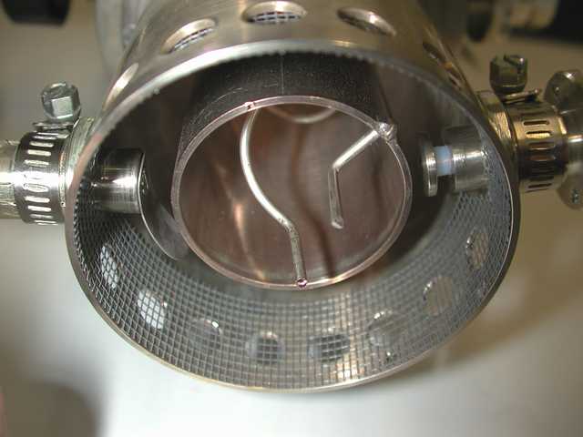 23cM-GS35-ff-cat.JPG |
 23cM-GS35-cav1.JPG |
 23cM-GS35-kat3.JPG |
 23cM-GS35-kat2.JPG |
After testing, holes were enlarged to increase airflow |
 23cM-GS35part4.JPG |
 23cM-GS35-kat.JPG |
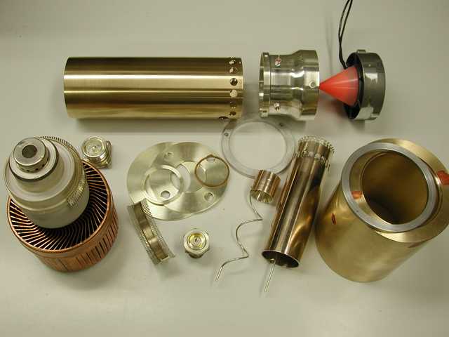 23cM-GS35parts.JPG |
 23cM-GS35-kat1.JPG |
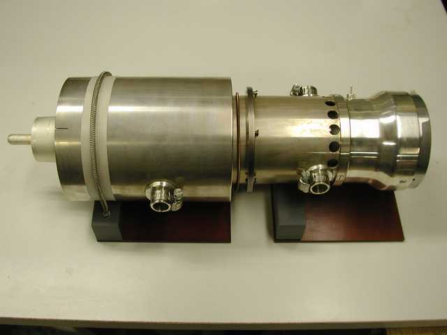
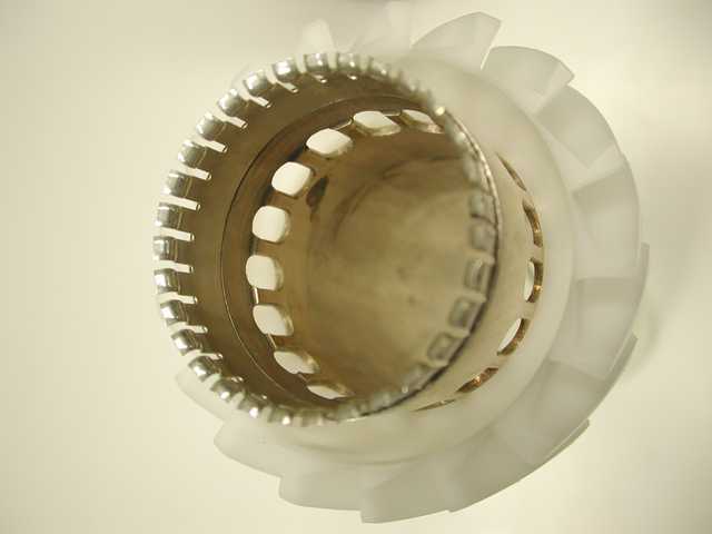
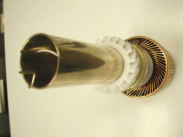
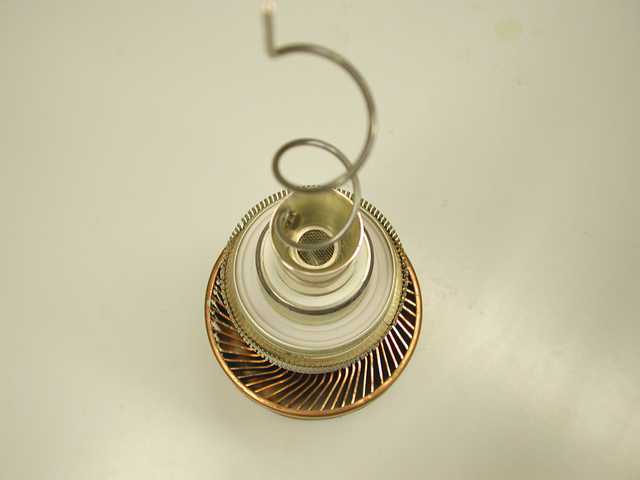
The grid connection is 2 half rings of finger stock, which slide into the tube |
 23cM-GS35part3.JPG |
 23cM-GS35part1.JPG |
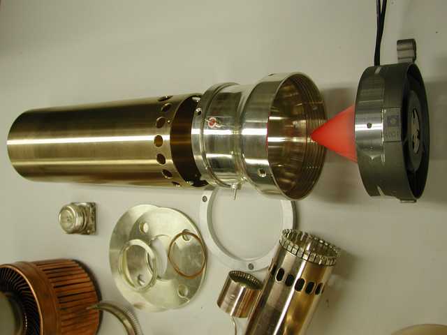
After the first test, I changed the airflow direction. The air is now pushed into
the outside holes and pulled out by the second blower. Working now to cool down
the grid tube and the air stream with a Peltier element. Another option is to cool the
grid tube outside with water cooling and also inside water cooling on the cathode must
be possible. There is a lot off heat to exchange, due the low efficiencies on 23 cM. I
continue to work to reduce thermal drift problem.
|
| Page: 1 2 3 |
| [ Prev ] [ Next ] |
go to the top