GS-35B Power Supply Controller
by
VK8RH
Click on callsign for e-mail

Click on picture for schematic diagram.

The power control circuit board controls the system sequencing for power up/down. The micro program has been completed and fully tested and provides the functionality as described below:

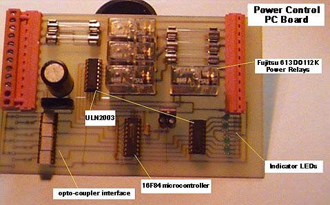
The circuit board is based on a PIC16F84 microcontroller. The micro monitors the power on signal (opto-coupled) and when asserted turns on the fan relay.

After a 5 second delay the filament relay is turned on and a 3 minute filament timer is started. At the end of the filament delay the relay that controls the high voltage (either directly or via a contactor) is turned on and then starts another timer for the high voltage slow start delay. After 2 seconds the slow start relay operates and bypasses the current limiting resistor (47 ohm 50 watt). After this, the power supply is ready for use.

An input (opto-coupled) monitors any alarm conditions from the amplifier and if asserted immediately turns off the high voltage relay. To ensure that operation is immediate there is both a hardware control that operates immediately and a software control that latches the fault condition.

Another input (opto-coupled) is provided to reset the fault condition and re-apply high voltage.

A forth input (opto-coupled) is provided to turn off the power supply. The turn off sequence is a reverse of the turn off procedure. The high voltage is turned off then the bypass relay is turned off. After a short delay the filament relay is turned off. The fan continues to operate for 30 seconds after the filaments are turned off. All times are adjustable in software to accommodate different valve types and control requirements.

Circuit Description

Incoming mains power is applied to SK1 pins 1 and 3.

240VAC is applied to SK2 pin 5 via fuse F2 to supply the auxiliary power transformer.

16VAC derived from the auxiliary power transformer is applied to SK1 pins 9 & 10. This is rectified and filtered to provide 14 volts DC to operate the relays and is regulated down to 5 volts by IC5 (LM7805CT) to power the microcontroller. Unregulated 14 dolts DC is available on pins 11 & 12 to operate external circuits.

Control power is fed via fuse F1 to SK2 pin 2 and also to pins 3, 4 & 5 via relays RLA, RLB & RLC and fuses F3, F4 and F5.

Opto-couplers IC1 - IC4 provide isolation from the external interfaces to the microcontroller.

The microcontroller (PIC 16F84) controls the timing of the power startup and shutdown sequence together with the monitoring and control of overload conditions of the amplifier.

A copy of the HEX file for the 16F84 pic controller can be downloaded HERE.

Circuit Operation

The control board receives a low signal from SK3 pin 4 to turn the power on. This is coupled thru IC2 to pin 7 of the microcontroller. The controller detects the low signal and high signal to RB4 turning on the fan on led and a high to RA3 turning on the fan relay. Relay A operates and provides 240VAC via fuse F3 to SK2-3 to power the cooling fans.

After a delay of 5 seconds RB6 is forced to a high to operate the filament on led and RA2 is forced to a high to operate the filament relay. 240VAC is provided to SK2-4 via fuse F4 to power the filament transformer.

After a delay of 120 seconds, RB7 is forced high turning on the HV on led and RA1 is forced high operating relay RLC. 240VAC is provided to SK2-6 to power the HV circuits or external HV control relays.

After a further delay of 2 seconds RB5 is forced high operating the Mains delay led and RA0 is forced high operating relay RLD - HV slow start relay. This relay bypasses the slow start resistors in the primary of the HV transformer.

At this stage the amplifier should be operating normally.

When an overload signal is received via SK3-2 the signal is coupled via IC1 to RB0 of the microcontroller.

This is programmed to use the interrupt signal of the microcontroller but due to the architecture of the 16F84 and immediate interrupt response cannot be guaranteed. To overcome this the overload signal is also connected to the junction of the ULN2003 drivers connected to port RA1. This immediately forces the HV relay to drop out thereby protecting the system. After the interrupt is serviced by the microcontroller the HV relay (RLC) and the slow start relay (RLD) are turned off and the system waits for an overload reset signal via SK3-8.

When a low is applied to SK3-8 this is coupled to RB3 of the microcontroller and starts the HV startup sequence again operating relays RLD then RLD after 2 seconds.

To shut the amplifier down a low is applied to the power off connector SK3-6. The low signal is coupled to RB2 of the microcontroller. This immediately turns off the HV (RLC and RLD), then after 2 seconds turns off the filament transformer (RLB). The cooling fans are left running for a period of 30 seconds before shutting off (RLA).

The controller resets and waits for the power on signal again.

As the main control signals are all opto isolated they can be remote from the power supply.

For lower power systems the PCB can be used to directly operate the relevant power transformers but for systems over several hundred watts, external relays or contactors should be used with RLC & RLD operating the external contactors.


home home home
go to the top