GI-7B in a GLA-1000
by
W4EMF
Click on callsign for e-mail

Scroll down to see pictures and narrative describing GLA-1000 converted to use the Russian GI-7B triode, below the schematic diagram and notes.

Notes from the schematic diagram
100KW, 2W resistor added to cut off plate current in standby.
23W, 10W wire wound resistor added to bring filament voltage to proper 12.6V.
Orignal zener used for operating bias. It will not survive long, key-down tune ups!
No parasitic oscillation instability noted on any band.
1000 pF substituted for original 200pF to pad load capacitor on 80M.
Three 1 MW, 2W resistors added to HV metering to make meter read 3KV, full scale.
Two K2AW (6KV @ 1A) diode modules were used for voltage doubler circuit rectifiers.
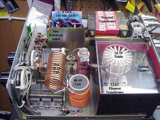
Six 150uF, 450VDC Electrolytic Capacitors used for doubler circuit filter.
Six 100KW, 2W flame-proof resistors across capacitors for equalization and bleeders.
Two 1KV, 1A "back-to-back" diodes added across meter to protect it.
10M tuned input circuit added to input PC board; see notes, below.
20-15-10M output coil (L1) lengthened and retapped; see photo and narrative.
 

A plexiglass box was built around tube with opening directly above tube. Cooling is quite sufficient with this system.


The original operating bias circuit will smoke if long "key-down" tune-ups are done. Use a pulser (e.g., keyer set for continuous dits) and no problem should be experienced.


The new output inductor is the same diameter and wire size as the original unit. The length is longer (see narrative, below).


The 10 meter input inductor is 8 turns of #24 enameled wire .250" inside diameter. Turns are spread and/or compressed to attain best input SWR. No toriod was used.


T/R relay K1 was changed to a smaller and faster 3PDT unit with a 12VDC coil, the added contacts used to cut-off the tube during standby (see narrative, below).


Filament choke is bifilar-wound #19AWG wire filling a 4" x 3/8" Amidon ferrite rod (#43 mix). Wind on 3/8" dowel, transfer to rod to prevent breakage. Cover with heatshrink.


Typically, 60W drive should yield around 600W out with PA tuned for maximum output and should run cool under normal use.

Click on picture for zoom

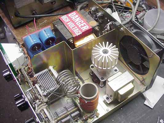
Original tank circuit, new tube and socket, new bulkhead

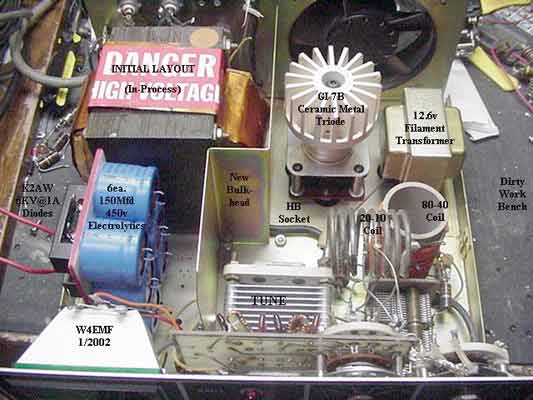
Front view of first picture, with lables added for clarity

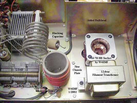
RF compartment - original tank; new tube socket installed

Orignal tank, new RF choke and parasitic choke with tube

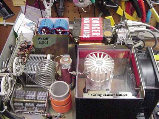
Cooling box installed
 

New tank coil installed

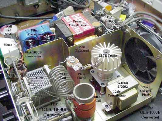
Top-Front view of PA
 

PA bottom, showing cathode wiring


The GLA-1000 series of amplifiers were good small amps but to often suffered at the hands of those operating them. They were not without problems as received thus compounding the grief of many owners. My amplifier was acquired inoperative and minus tubes. It had the general repairs found in most of these units. The diodes and filter capacitors had been replaced and were flopping around in their designated area. My intention was to modify this amplifier to utilize the Russian GI-7B ceramic metal triode. The B+ voltage was too low for the GI-7 so the first portion of the project was to build a voltage double circuit. The unit originally used a full wave bridge circuit generating around 1150 volts no load. The new supply completed delivers 2275 volts no load and has 25 Mfd @ 2700 volts of filtering. Six 150 Mfd @ 450volt electrolytic capacitors are paralleled with 100K ohm resistors for equalization and wired in series.

This done, I started work on the RF section. The circuit board with the four sockets and plate choke were removed. A steel plate (.028” thick) was made and placed over the hole left when the circuit board was removed. Layout was the next consideration. The GI-7B, a 12.6v @ 3amp transformer, the plate choke, and by-pass capacitor must be located on the plate. A steel bulkhead (.028” thick) was fabricated and placed between the power supply components and RF compartment to better isolate the two functions.

The final layout for the tube, transformer, and choke was determined. The tube was placed behind the tune capacitor and the transformer between the tube and right hand side of the amplifier. The plate choke (original) was placed between the tube and the tune capacitor. The DC blocking capacitor was attached to the top of the choke. The parasitic suppressor was connected from top of the choke to the anode of the GI-7.

On the bottom side of the amplifier a bifilar wound filament choke was installed between the filament windings and the home brew tube socket heater and heater/cathode collets. The transformer side of the choke is bypassed with two .02 @ 500 volt disc ceramic capacitors. A 23 ohm 10 watt resistor was installed in one lead of the primary of the filament transformer to reduce the secondary voltage to the specified 12.6 volts under a 2amp load. Check voltage at the heater collets on the tube sockets. The miniature coaxial cable from the relay was reconnected through two .01 @ 500 volt disc ceramic capacitors in parallel to the cathode collet. The 8uhy choke used previously for the B- return from the cathodes was connected to the cathode collet. The wire from the bypassed end of the choke was wired to a 100K-ohm resistor connected in series with the original 24-volt zener diode used for operating bias. Two wires were attached to each end of the resistor and routed to the change over relay contacts. The contacts short the resistor out when the amplifier is keyed allowing the operating bias to hold the idling plate current to around 50-80 milliamperes. The 100 K ohm resistor cuts off DC plate current flow when the amplifier isn’t being used.

Every GLA-1000 series amplifiers I have worked on did not have this "cut-off" circuit installed as received new from the manufacturer. The absence of this feature caused the demise and premature death of many sets of 6LQ6 sweep tubes. Example: .080 ma of plate current X 1100volts equals 88 watts of power being dissipated by the tubes while they were not in use. This is nearly equal to the total dissipation rating for the four tubes. This accounts for the amplifier quickly using up the tubes. There were several excellent modifications offered by numerous amateur operators to remedy this design oversight.

The next problem encountered was the tank circuit. By elevating the voltage from 1200 to 2275 and reducing the plate current from nearly 1 ampere to .500ma, the plate load impedance was changed form 800-900 ohms (1200v) to 2800 ohms (2250v). The problem occurring was that the TUNE and LOAD capacitors were of insufficient value to handle the impedance. There is not enough inductance in the circuit for the higher plate load impedance. My solution was to remove the horizontal coil for 20-15-10 meters and wind another coil from 1/8” copper tubing. This coil was tightly wound on a 1 1/4” diameter form. The turns were then evenly spaced. A total of 13 turns was inserted back into the tank circuit using the same mounting methods. The coil was tapped 5 ½ turns (for 10 M) from the end connected to the TUNE capacitor and 8 ½ turns (for 15M) from the same point. The 20M tap stays in the same location. Flat strap was substituted for the small diameter wire used for the original taps. A 1000pf doorknob capacitor was substituted for the 200pf unit used as load capacitor padding for 80 meters. The addition of this coil will bring the tank circuit back into range (80 -10 meters). Both 80 and 40 meters will now tune with the existing TUNE and LOAD capacitor. Adding the new inductor corrects the problem of insufficient inductance on 80 and 40 allowing the amplifier to tune properly for the new plate load impedance. Additional padding can be added for 40 meters if needed by installing an additional contact on the band switch and adding the proper value of capacitance needed. This may occur on some units due to engineering design changes made during the manufacturing cycle of the GLA-1000 series of amplifiers. A total refit of the factory tank coil can be attempted if additional adjustments are needed.

Good luck on your conversion. Conventional techniques have been used in this modification and additional study in the Handbook and other texts may be required. This short article is not all-inclusive and will not cover every situation encountered. Variation from unit to unit will also come into play at times.

Another reminder; Please be mindful of lethal voltages present in this amplifier and use caution while working on this project.

Lawson Summerrow / W4EMF

3/30/03

home back home
go to the top