|
It is fairly common knowledge among hams operating the HF bands that the MLA-2500 is a
workhorse amplifier, but the fear of losing the famous and fragile EIMAC 8875 tubes resides
in the forefront of all operators’ minds.
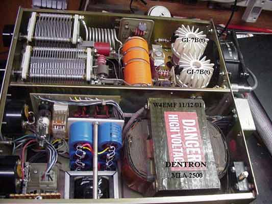
This short article covers some of the needed information to convert this amplifier to use
the Russian GI-7B and GI-7B(t) tubes. The B(t) version was made specifically for use in
military tanks and is physically more rugged as indicated by its physical appearance.
My amplifier was acquired minus the two 8875 tubes. It was in excellent physical condition
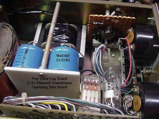
and was in original condition. The high voltage section was rebuilt using six new 150Mfd
@ 450v electrolytic capacitors and two K2AW 6KV @ 1A brick diodes. Old capacitors, diodes,
and equalizing capacitors were removed and replaced. Physical layout must be a consideration,
as space is needed for a 12.6v ct @ 4a filament transformer and an operating bias module.
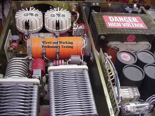
After some lengthy experimentation a layout was determined (view photo of power supply
compartment). There was no room to spare, but all the components were carefully fitted
inside the available area. Testing was performed and all the modifications except the bias
module were found to be functioning properly. Testing the bias module will be performed
following installation of the tubes.
It was necessary to remove the change over relay and move it over the center bulkhead and
out of the way temporarily. Next the wattmeter pick-up board was removed and set aside and
wire tagged until a new location could be determined. The wires were disconnected from
the tube sockets. The green wire going to the filament connection must be removed and tied
to the other green wire going to the meter lights and other associated circuitry requiring
6.3v ac. The yellow wire (B-) must be disconnected from the cathode pin of the sockets.
If applicable, the brown wire from the grid resistor (from grid strap to ground) that goes
to the meter switch circuit board must be disconnected. Some models have the grid resistor
mounted on the s metering switchboard. Ignore the previous step if this resistor is mounted
on the switchboard.
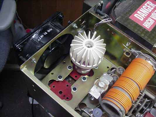
The next step required is removal of the 8875 sockets. I decided to cut the metal out the
sockets are mounted on to allow room for some homebrew sockets I had constructed earlier.
See the “Gutless” picture. The metal was cut out with a good quality pair of sheet metal
cutters. Following removal of this material, it was necessary to straighten the remaining
material left on the chassis. Metal cutters tend to bend the sheet metal as they cut.
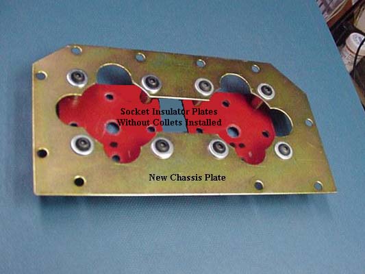
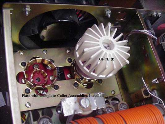
I used a small vise to clamp each prong and eventually straightened all of them. Next
I took the socket plate and laid it on the original chassis to determine where to place
mounting holes for the spacers to mount the plate to the original chassis (see picture).
Hole locations were determined and punched in the socket plate. They were transferred
to the chassis and it was drilled out to suit. The socket plate was then mounted to the
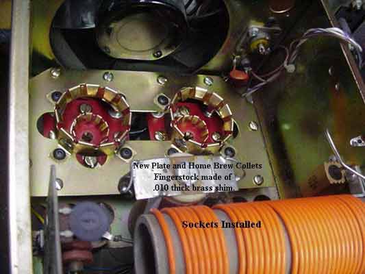
chassis on ˝” metal stand-offs. The components previously made to construct the sockets
were installed on the plate (see picture).
The GI-7B tubes were installed and the determination was made to replace the old change
over relay with a smaller and faster unit. It was mounted much lower in the same location.
The wattmeter pick up circuit was remounted between the wire coming off the end of the
tank coil and the relay (see picture). It is tight but will fit. The tubes were removed
and the amplifier turned over to wire the bottoms of the sockets. A filament choke was
added between wires coming from the filament transformer in the power supply compartment.
It is large enough to handle the 4 amps of filament current required by the tubes and small
enough to fit between the chassis and the bottom cover when installed. It is bypassed on
the supply side at the terminal strip with two .02 @ 500v disc ceramic capacitors. The
leads from the choke are attached to the jumpers from the heater and heater/cathode
connections. A pair of .02 @ 1KV disc capacitors run from a terminal strip to each
cathode connection on the sockets. The mini coax from the changeover relay is connected
to the terminal strip at the junction of the two .02 capacitors. The shield is connected
to the ground lug. The yellow wire is attached to the orange wire at the terminal strip
going to the filament transformer center tap. This is the (B-) return path. The ALC
pick-off circuit must be reconnected to the cathode. The temperature switch is mounted
near the ceramic body of the left tube on the side opposite the fan.
Parasitic suppressors are connected to the tube fins by using two modified Fahnstock clips
(see pictures).
Horizontal cooling fins were installed later in the project to replace the original anode
coolers. No significant improvement was noted in the cooling. The original anodes were
used with a plastic bulkhead installed between the tubes and tank circuit. This contains
and deflects the air up and down with the majority of the air escaping from the top. If
the tubes become excessively warm the temperature circuit will place the fan on high speed
until the temperature sensor opens again.
Additionally, a high wattage operating bias circuit is required to tame the high static
plate current the GI-7B tubes will draw. Typical bias voltage will run between 24-30
volts depending on the desired resting plate current.
All details encountered in this experiment could not be written in this short article.
It would be impossible to accomplish this. Some of the details and obstacles you will
encounter quite possibly may not parallel the problems I encountered in this project.
Undertaking and completing a project such as this is rewarding but often times exasperating.
There is no cut and dried way to accomplish a project such as this. Your way might be far
superior to my methodology and execution.
Additionally, it is impossible for me to answer all questions submitted by email, as I
cannot see your project. This article is written to share some basic methods I used
successfully. It is not all-inclusive, nor meant to be, and the obstacles encountered
in a project of this magnitude can be legion in number.
Good luck,
Lawson Summerrow / W4EMF
|